

If you buy or specify low-voltage switchgear, you will see the letters IEC 61439 on almost every datasheet and declaration of conformity. This international standard defines how low-voltage switchgear and controlgear assemblies must prove their safety and reliability. Yet many purchasers treat it as a stamp they never read. This guide explains what IEC 61439 actually requires, and it focuses on the two checks that matter most: design verification and routine verification. Read it, and you can judge a supplier’s evidence instead of trusting a logo.
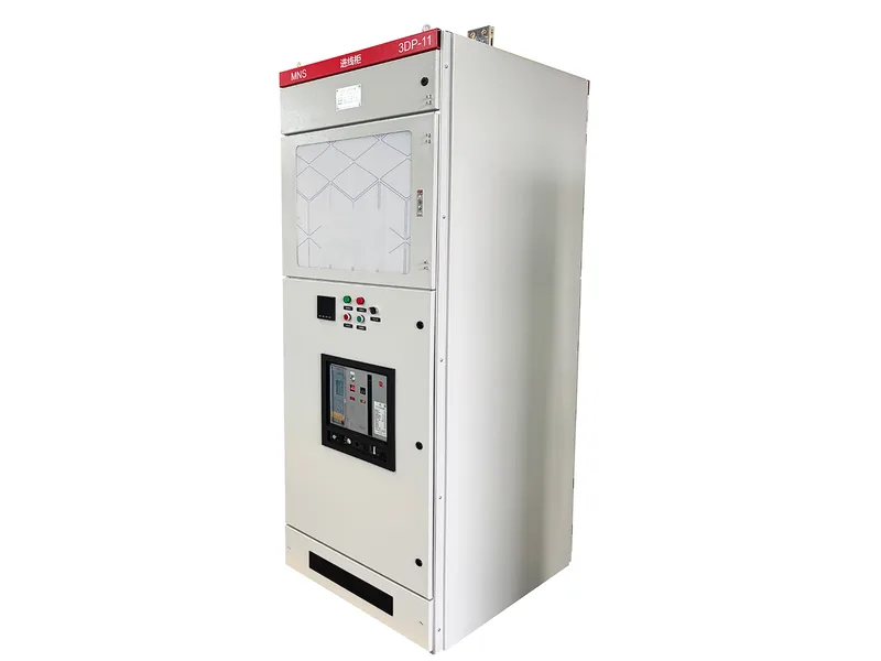
What IEC 61439 Is and Why It Replaced IEC 60439
IEC 61439 is the current family of standards for low-voltage switchgear and controlgear assemblies, and it covers equipment up to 1000 V AC and 1500 V DC. It replaced the older IEC 60439 series, and the change was not cosmetic. Under 60439, buyers often assumed that a “type test” on one panel covered a whole range of similar panels. IEC 61439 closed that gap: verification must now prove the *specific* assembly you receive meets the standard, not just a look-alike from the catalogue.
The standard splits into parts. IEC 61439-1 gives the general rules, while IEC 61439-2 covers power switchgear and controlgear assemblies (the kind you find in substations, factories, and commercial buildings). Other parts deal with distribution boards, busbar trunking, and site assemblies. So when a supplier says a panel “complies with IEC 61439,” ask which part, and ask what verification evidence backs the claim.
The Two Pillars: Design Verification and Routine Verification
IEC 61439 organises its proof into two pillars. Design verification confirms the *design* is sound. Routine verification confirms that the factory assembled *each individual unit* correctly. You need both, because they answer different risks. However, a panel can have a proven design and still leave the factory faulty if someone skips the routine checks, so ask for both sets of records.
Our guide to switchgear factory acceptance test covers the witness tests you can request on top of these; the verification below is the baseline the standard mandates.
Design Verification — What It Covers
Design verification proves that the assembly’s design meets every relevant requirement of the standard. The manufacturer performs it on a representative sample, and once it passes, it stays valid for that design. Here are the key items it covers.
Dielectric and Insulation Properties
The test lab applies a dielectric stress to the assembly and checks clearance and creepage distances, so the insulation does not break down under the rated voltage, including transient overvoltages. The rated insulation voltage (Ui) and rated impulse withstand voltage (Uimp) set the bar here. For a 400 V system, Ui commonly reaches 690 V or higher, which gives you margin.
Temperature-Rise Limits at Rated Current
At its rated current, no part of the assembly may exceed a safe temperature. IEC 61439-1 sets temperature-rise limits that depend on the material. It limits bare copper connections to about 70 K rise, allows 75 K for tinned surfaces and 80 K for silver- or nickel-plated ones, and limits insulating materials by their class. In fact, a verified design means the busbars, connections, and enclosures proved they stay within these limits at full load, not just on paper.
Short-Circuit Withstand (Icw and Ipk)
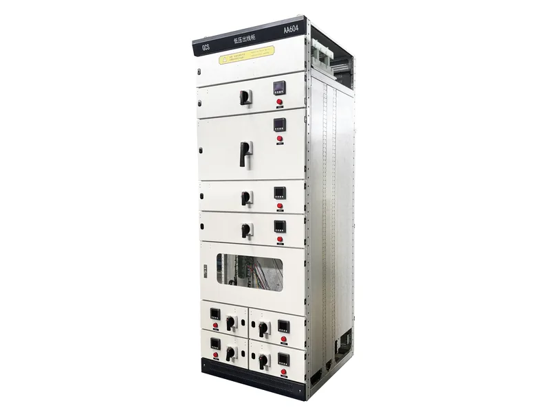
The assembly must survive a short circuit without falling apart or creating a hazard. Two rated values matter. The rated short-time withstand current (Icw) is the current the assembly can carry for a set time, usually 1 s. The rated peak withstand current (Ipk) must at least match the peak of the prospective short circuit. For 50 Hz systems the peak factor n is commonly 2.2, so Ipk is roughly 2.2 × Icw. Real LV assemblies span a wide range — for example, a GCK-type board might hold 30 kA Icw, while a GCS-type reaches 65 kA Icw with a 143 kA peak.
Effectiveness of the Protective Circuit
The protective conductor path carries fault current to earth, so it must stay low-impedance and robust enough to survive a fault. That is what makes the upstream breaker actually trip instead of the enclosure heating up. Design verification confirms the continuity and the mechanical security of every joint in that path.
Clearances, Creepage, Mechanical Operation and IP / Forms of Separation
The standard also checks electrical clearances and creepage distances, the mechanical operation of disconnectors and withdrawable parts, and the degree of protection (IP) plus internal separation (Forms 1 to 4). In addition, forms of separation decide how much a fault in one compartment stays contained, and that directly affects personnel safety.
Three Accepted Methods: Test, Calculation, Comparison
Here is a useful point for buyers: IEC 61439 does not force a full test for every variation. You can prove design verification by (1) testing, (2) calculation or design rules, or (3) comparison with a reference design already verified. Method 3 is why a manufacturer can offer many configurations from one proven platform, provided the supplier documents the comparison. So ask which method the supplier used for the exact variant you buy.
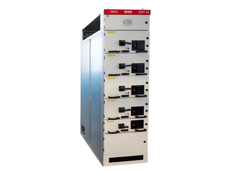
Routine Verification — What Happens to Every Assembly
Where design verification proves the design, routine verification proves the unit. The factory runs routine checks on every assembly before it leaves, and this is the layer most often cut when a supplier is in a hurry.
Visual Inspection
The assembler checks that the assembly matches the documentation: correct components, ratings, wiring, and labelling; no loose parts; correct IP and separation; and a properly connected protective conductor. It sounds basic, but in practice most field failures trace back to something a careful visual check would have caught.
Dielectric Test of the Main Circuit
A power-frequency withstand test stresses the main circuit after assembly to confirm insulation integrity. It catches damaged insulation, incorrect clearance, or a trapped tool left inside the panel.
Continuity of the Protective Circuit and Functional Check
The assembler measures the resistance of the protective circuit to confirm the earth path is sound, then runs a functional check on interlocks, indicators, and trip units. A low voltage switchgear assembly that passes these checks is ready to energise; one that skips them is a gamble.
Rated Values You Will See on the Verification Documents
The verification records and the declaration of conformity list rated values. If you know what they mean, then you can compare offers. The table below maps the common ones to what they tell you.
| Rated value | Symbol | What it tells you |
|---|---|---|
| Rated operational voltage | Ue | The system voltage the assembly is built for (e.g. 400 V) |
| Rated insulation voltage | Ui | The insulation’s maximum continuous rating (e.g. 690 V) |
| Rated impulse withstand | Uimp | Resistance to transient overvoltages |
| Rated current | In / Icw(busbar) | Continuous current the busbar and feeders carry |
| Short-time withstand current | Icw | Fault current the assembly survives for a set time (e.g. 1 s) |
| Peak withstand current | Ipk | Asymmetric peak the assembly must survive |
| Degree of protection | IP | Ingress protection of the enclosure (e.g. IP40) |
| Forms of separation | Form 1–4 | How compartments are separated for fault containment |
So when two quotes look similar, line these symbols up. Different Icw or IP values at the same price usually explain the gap.
How Installation Environment Affects the Verification
IEC 61439 assumes a reference environment: up to 40 °C ambient, up to 2000 m altitude, and a defined pollution degree. Real sites are rarely that tidy, so you need to read the verification with your site in mind.
Ambient Temperature and Derating
If your switchroom runs hotter than 40 °C, the assembly may need derating or a higher temperature-rise classification, because the standard references its limits to that baseline. A panel verified only at the default may overheat in a tropical or poorly ventilated room.
Altitude, Humidity and Pollution Degree
Altitude works the same way. Above 2000 m, air is thinner and creepage distances need correction. High humidity and a heavy pollution degree drive the choice of insulation and enclosure. If your project is coastal, high-altitude, or industrial, state it in the enquiry so the verification actually covers your condition — a point we also stress in ourswitchgear RFQ checklist.
Documents to Request From the Supplier
Finally, turn a compliance claim into proof by asking for these in writing:
- Declaration of conformity to IEC 61439-1 / -2
- Design verification record (test, calculation, or comparison file)
- Routine verification records for your specific serial-numbered unit
- Single-line and general arrangement drawings
- Bill of materials, so you can confirm the verified components were fitted
- Temperature-rise and short-circuit verification summaries
In short, a price without these is a promise. With them, you hold a verified offer you can defend.
What to Specify So the Supplier Can Prove Compliance
IEC 61439 verification is only as good as the specification behind it. To avoid the omissions that sink a quote, state a few things clearly in your enquiry. List the rated voltage and Ui, the continuous current for busbar and feeders, and the required Icw and Ipk. Then add the IP and forms of separation, the ambient temperature and altitude, and the pollution degree. Give the supplier those, and as a result they can return a declaration and verification records that match your site, instead of a generic certificate that does not. If you are still deciding between medium and low voltage options, our guide to choosing medium voltage switchgear frames the trade-offs.
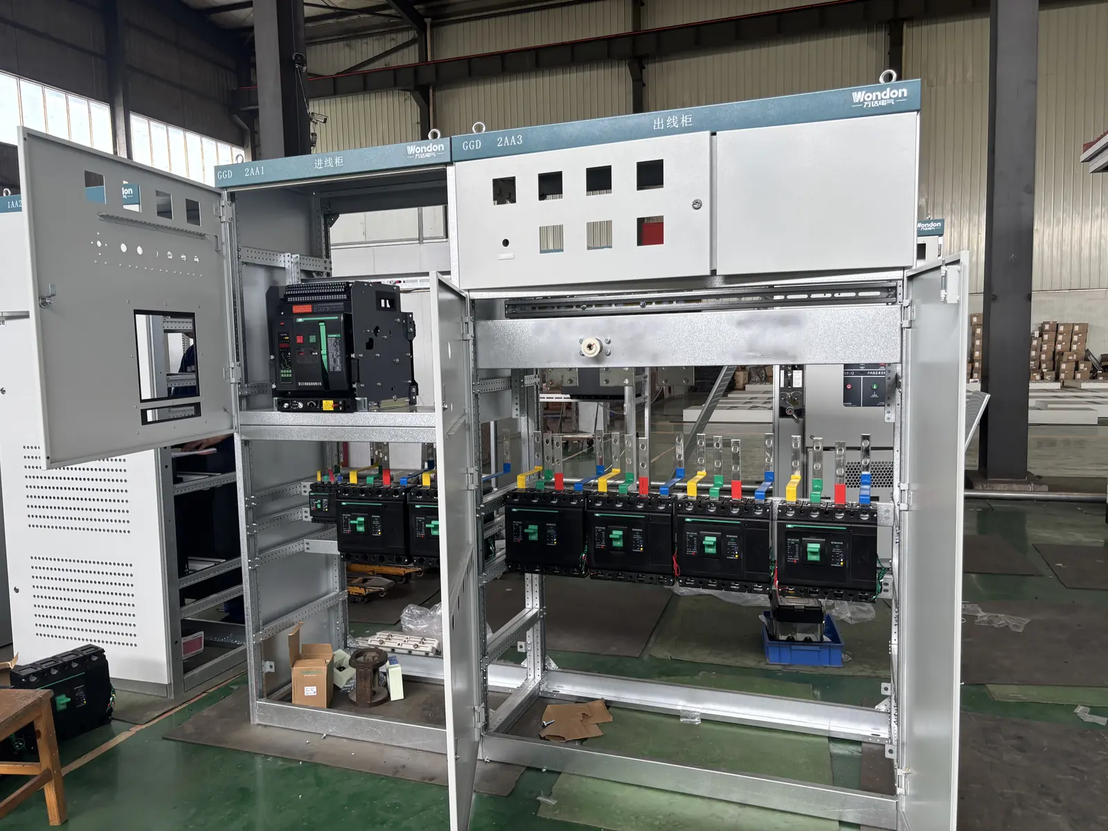
Documents to Request From the Supplier
Finally, turn a compliance claim into proof by asking for these in writing:
- Declaration of conformity to IEC 61439-1 / -2
- Design verification record (test, calculation, or comparison file)
- Routine verification records for your specific serial-numbered unit
- Single-line and general arrangement drawings
- Bill of materials, so you can confirm the verified components were fitted
- Temperature-rise and short-circuit verification summaries
In short, a price without these is a promise. With them, you hold a verified offer you can defend.
What to Specify So the Supplier Can Prove Compliance
IEC 61439 verification is only as good as the specification behind it. To avoid the omissions that sink a quote, state a few things clearly in your enquiry. List the rated voltage and Ui, the continuous current for busbar and feeders, and the required Icw and Ipk. Then add the IP and forms of separation, the ambient temperature and altitude, and the pollution degree. Give the supplier those, and as a result they can return a declaration and verification records that match your site, instead of a generic certificate that does not. If you are still deciding between medium and low voltage options, our guide to choosing medium voltage switchgear frames the trade-offs.