

Medium voltage switchgear is electrical equipment used in power systems with voltage levels from 3kV to 40.5kV. It receives, distributes, controls, and protects electrical energy within power networks.
By integrating components such as circuit breakers, disconnect switches, and protection devices, medium voltage switchgear manages electrical equipment and power transmission lines. It can also quickly interrupt fault currents caused by short circuits, overloads, and other abnormal conditions, helping maintain safe and stable grid operation.
In this medium voltage switchgear explained guide, we will introduce its applications, classifications, main components, operating principles, and key technical features to help you better understand this essential power distribution equipment.
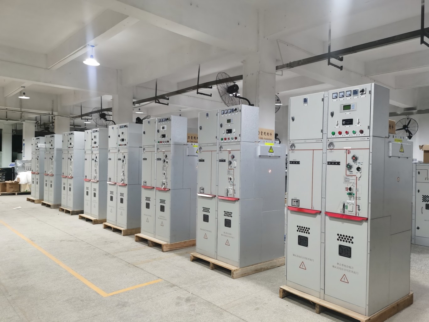
Applications of Medium Voltage Switchgear
Due to its high safety, flexibility, and reliability, you can see this equipment in various industries and power projects.
1. Industrial Power Distribution Systems
Medium voltage switchgear is commonly used in industrial power distribution systems.
It supports power distribution, motor control, equipment protection, and fault isolation.
As a result, it helps industrial equipment operate continuously and safely.
2. Renewable Energy Projects
In solar PV projects, medium voltage switchgear usually works together with step-up transformers, protection devices, and grid connection equipment.
It collects generated power, controls power distribution after voltage conversion, and provides protection during grid connection.
As a result, it supports the safe and efficient integration of renewable energy into the power grid.
3. Power Plants and Energy Facilities
Power plants use medium voltage switchgear for internal power distribution, feeder control, and equipment protection.
It allows operators to quickly isolate faulty equipment and limit the impact of failures on the entire electrical system.
4. Commercial Buildings and Infrastructure
Medium voltage switchgear provides stable and reliable power distribution for commercial buildings and public infrastructure.
Its protection and monitoring functions also help reduce outage risks caused by equipment failures.
5. Power Distribution Networks
By controlling and protecting medium voltage circuits, switchgear helps maintenance teams quickly locate and isolate fault areas.
At the same time, unaffected areas can continue receiving power, improving the overall reliability of distribution networks.
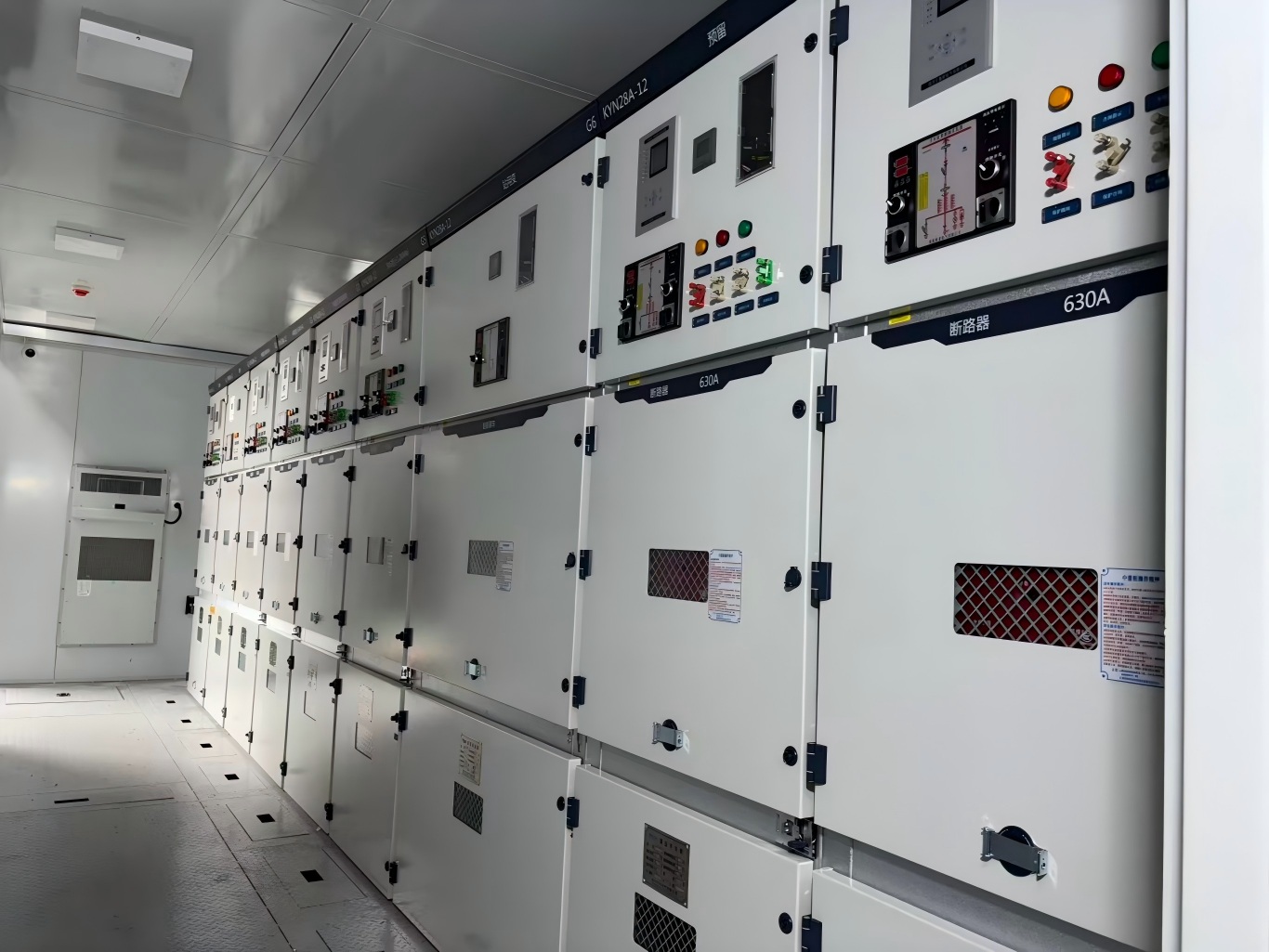
Classification of Medium Voltage Switchgear
We can classify medium voltage switchgear based on three main factors: structure type, circuit breaker installation position, and insulation technology.
1. Classification by Structure Type
Armored Type
Armored switchgear uses metal partitions to separate internal compartments, and each compartment has proper grounding protection.
Common examples include KYN series and KGN series switchgear.
Compartment Type
Compartmental switchgear uses one or more non-metallic partitions to separate different sections.
The JYN series represents a typical example of this type.
Box Type
Box-type switchgear uses a metal enclosure with fewer internal compartments compared with armored and compartmental switchgear.
The XGN series belongs to this category.
2. Classification by Circuit Breaker Installation Position
Floor-Mounted Type
In floor-mounted switchgear, operators install the circuit breaker truck on the floor and push it into the switchgear cabinet.
Withdrawable Middle-Mounted Type
In this design, the circuit breaker truck sits in the middle section of the switchgear.
Operators need a loading device to install and remove the circuit breaker truck.
3. Classification by Insulation Type
Based on insulation technology, medium voltage switchgear mainly includes:
- Air insulated metal enclosed switchgear
- SF₆ gas insulated metal enclosed switchgear
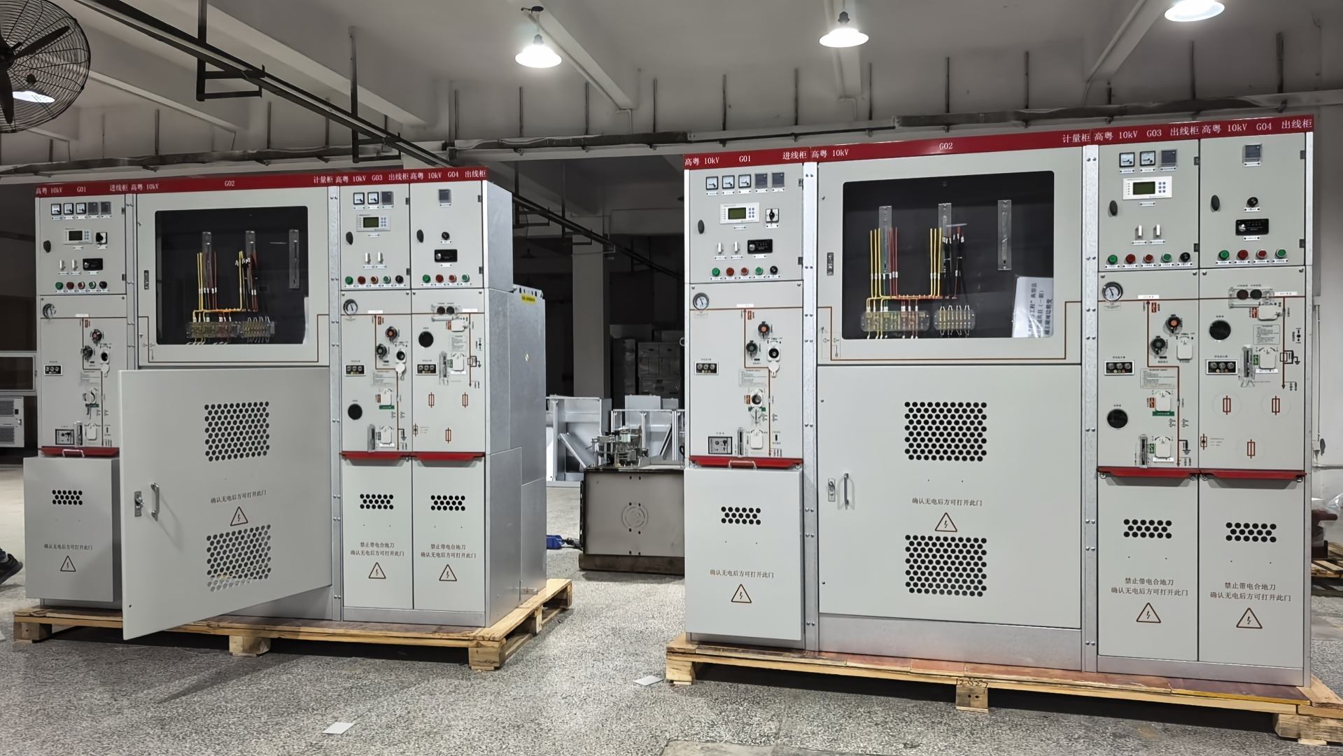
KYN Medium Voltage Switchgear
KYN series medium voltage switchgear, also known as metal-clad withdrawable switchgear, is an indoor complete switchgear assembly designed for three-phase AC 50Hz power systems with rated voltages from 3kV to 40.5kV.
It is widely used in power plants, substations, industrial and mining enterprises, and other applications for receiving and distributing electrical energy.
Meanwhile, it provides functions such as circuit control, protection, monitoring, and fault isolation.
Structure of KYN Medium Voltage Switchgear
Among different types of medium voltage switchgear, KYN switchgear is one of the most widely used solutions.
It mainly consists of two parts: the fixed cabinet body and the withdrawable components, also known as the circuit breaker truck.
1. Cabinet Body
The enclosure and internal partitions of KYN switchgear use aluminum-zinc coated steel sheets.
This cabinet structure provides high manufacturing accuracy, excellent corrosion and oxidation resistance, strong mechanical strength, and an attractive appearance.
The modular assembly design uses rivet nuts and high-strength bolts for connection, ensuring accurate dimensions and reliable installation.
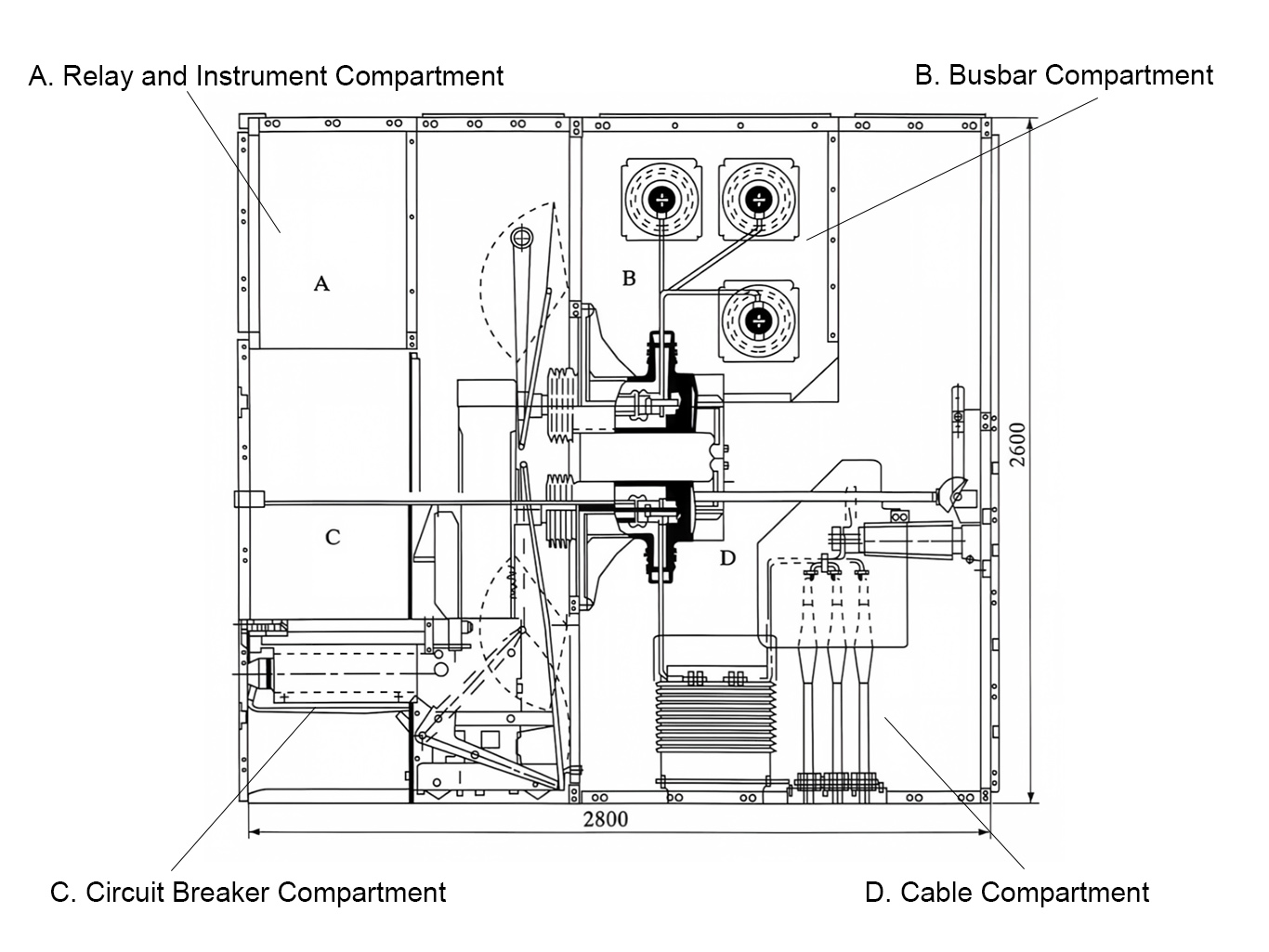
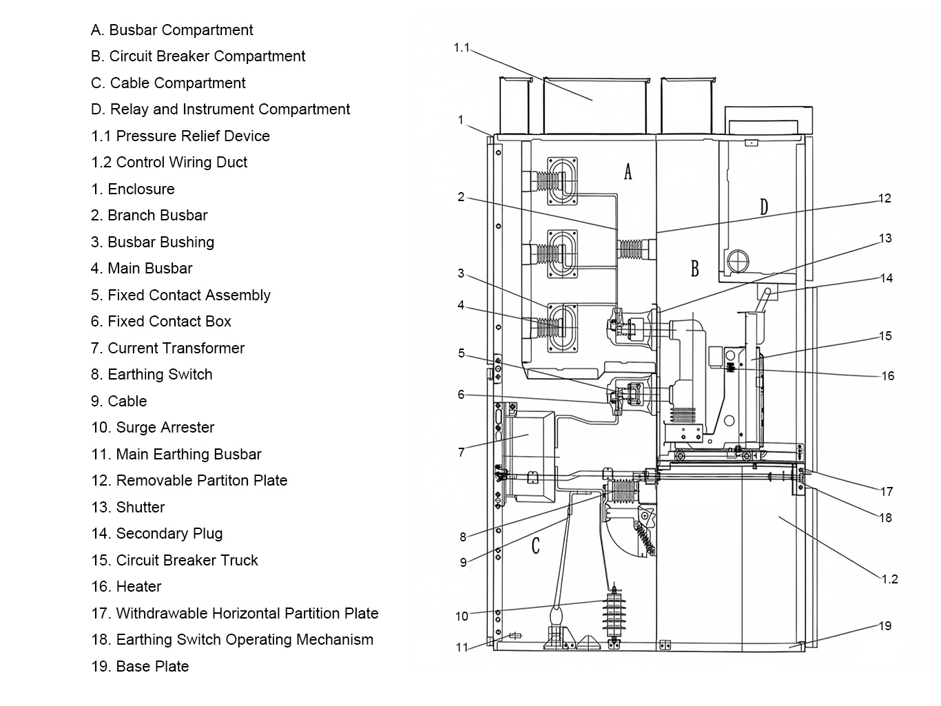
Internal partitions divide the switchgear cabinet into several independent compartments, including:
- Circuit breaker compartment
- Busbar compartment
- Cable compartment
- Relay and instrument compartment
Each compartment has an independent grounding system to improve operational safety.
2. Busbar Compartment
The busbar compartment is located in the upper rear section of the switchgear cabinet.
It accommodates three-phase high-voltage AC busbars and connects them to the static contacts through branch busbars.
All busbars have insulation sleeves for protection.
When busbars pass through internal partitions, special busbar bushings secure them in place and maintain proper insulation.
If an internal arc fault occurs, the compartment structure helps prevent the fault from spreading to adjacent cabinets while maintaining the mechanical strength of the busbar system.
3. Circuit Breaker Compartment (Withdrawable Truck Compartment)
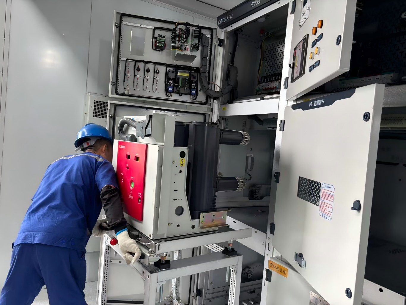
TThe circuit breaker compartment features dedicated guide rails that allow the circuit breaker truck to move smoothly between different operating positions.
The withdrawable truck can move between the service position and the test position.
A shutter mechanism on the rear wall isolates the static contacts.
When the circuit breaker truck moves from the test position to the service position, the shutter opens automatically.
When the truck returns to the test position, the shutter closes completely.
This design prevents operators from accidentally contacting live components and improves operational safety.
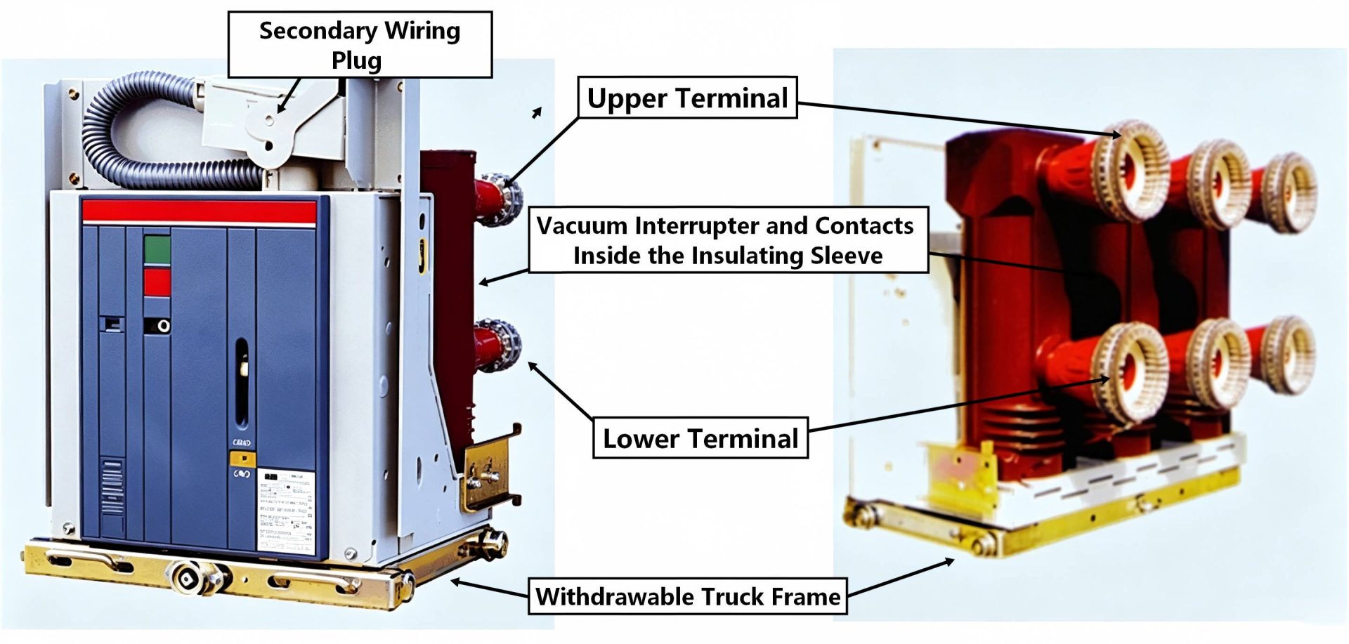
Types of Circuit Breakers Used in KYN Medium Voltage Switchgear
Based on the arc-extinguishing medium, circuit breakers mainly include the following types:
-
Oil Circuit Breaker
Oil circuit breakers include bulk oil circuit breakers and minimum oil circuit breakers.
Both types use transformer oil as the arc-extinguishing medium. The contacts operate in oil to connect and interrupt circuits.
-
Air Blast Circuit Breaker
Air blast circuit breakers use high-pressure compressed air to extinguish electrical arcs during circuit interruption.
-
SF₆ Circuit Breaker
SF₆ circuit breakers use sulfur hexafluoride gas as the arc-extinguishing medium to interrupt fault currents.
-
Vacuum Circuit Breaker
Vacuum circuit breakers open and close contacts inside a vacuum environment.
The vacuum provides excellent arc-extinguishing performance, allowing the circuit breaker to interrupt fault currents effectively.
-
Solid Gas-Producing Circuit Breaker
Solid gas-producing circuit breakers use special solid materials that generate gas under the high temperature of an electrical arc.
The generated gas helps cool and extinguish the arc.
-
Magnetic Blowout Circuit Breaker
Magnetic blowout circuit breakers use a magnetic field to move the arc into an arc chute.
The arc becomes stretched, cooled, and extinguished inside the chute.
Three Positions of the Switchgear Circuit Breaker Truck
The withdrawable circuit breaker truck in KYN medium voltage switchgear has three operating positions:
① Service Position
In the service position, the circuit breaker connects to the primary circuit.
After closing the circuit breaker, electrical power flows from the busbar through the circuit breaker to the outgoing feeder.
② Test Position
In the test position, operators can connect the secondary plug to the socket to provide control power.
They can perform circuit breaker closing and opening tests, and the corresponding indicator lights operate normally.
At this position, the circuit breaker disconnects from the primary circuit.
Therefore, operators can complete control operations without affecting the load side.
③ Maintenance Position
In the maintenance position, operators can also connect the secondary plug to the socket for control operations.
The circuit breaker remains disconnected from the primary circuit, allowing inspection and maintenance without affecting the load side.
4. Cable Compartment
The cable compartment contains various auxiliary components, including current transformers, grounding switches, surge arresters, and power cables.
A removable aluminum plate with cable openings is installed at the bottom of the compartment.
This design simplifies on-site cable installation and construction work.
5. Relay and Instrument Compartment
The front panel of the relay compartment contains various control and monitoring components, including:
- Microcomputer-based protection devices
- Operating handles
- Protection output links
- Meters
- Status indicator lights
The internal section of the relay compartment includes terminal blocks, DC power switches for protection control circuits, DC power supply units for protection devices, energy storage motor switches, and other secondary electrical components required for specific applications.
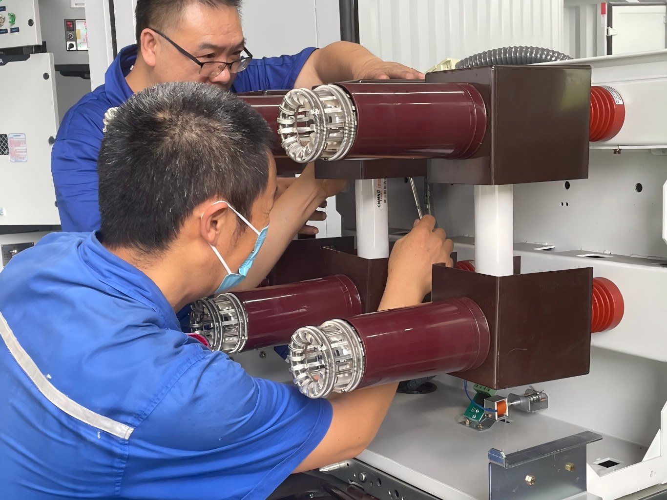
6. Mechanical Interlocking Device to Prevent Misoperation
KYN28 medium voltage switchgear uses a reliable interlocking system to protect operators and equipment from incorrect operations.
The main interlocking functions include:
a.
Buttons and selector switches on the instrument compartment door prevent accidental circuit breaker closing and opening operations.
b.
The circuit breaker truck can only perform closing and opening operations when it reaches the test position or service position.
After the circuit breaker closes, the interlocking mechanism locks the truck in place and prevents movement. This design avoids accidental insertion or withdrawal under load conditions.
c.
The circuit breaker truck can move from the test/maintenance position to the service position only after operators open the grounding switch.
Similarly, the grounding switch can close only when the circuit breaker truck remains in the test or maintenance position.
This interlocking design prevents accidental grounding of energized circuits and avoids circuit breaker operation when the grounding switch is closed.
d.
When the grounding switch remains open, the lower cabinet door and rear cover panel stay locked.
This prevents operators from entering energized compartments by mistake.
e.
When the circuit breaker truck is in the test or service position and control voltage is unavailable, the circuit breaker can only be manually opened and cannot be closed.
f.
When the circuit breaker truck reaches the service position, the interlocking mechanism locks the secondary plug and prevents removal.
g.
The switchgear system supports electrical interlocking between different cabinets to improve overall operational safety.
Main Technical Parameters of KYN Medium Voltage Switchgear
The commonly used KYN series medium voltage switchgear mainly includes two models: KYN28A-12 and KYN61-40.5.
Main Technical Parameters of KYN28A-12
| Parameter | Value |
|---|---|
| Rated voltage (kV) | 3/6/10 |
| Maximum operating voltage (kV) | 3.6/7.2/12 |
| Power frequency withstand voltage (kV) | 42 (1 min) |
| Lightning impulse withstand voltage (kV) | 75 |
| Rated frequency (Hz) | 50 |
| Rated current (A) | 630-4000 |
| Rated short-time withstand current (kA/4s) | 16-50 |
| Rated peak withstand current (kA) | 40-125 |
| Rated short-circuit breaking current (kA) | 16-50 |
| Rated short-circuit making current (kA) | 40-125 |
| Rated voltage of closing, opening and auxiliary circuits (V) |
DC 24, 30, 48, 60, 110, 220; AC 110, 220 |
| Protection degree | IP4X |
Main Technical Parameters of KYN61-40.5
| Parameter | Value |
|---|---|
| Rated voltage (kV) | 40.5 |
| Rated current (A) | 1250, 1600, 2000, 2500 |
| Rated frequency (Hz) | 50 |
| Rated short-time withstand current (kA) | 20, 25, 31.5 |
| Rated peak withstand current (kA) | 50, 63, 80 |
| Rated power frequency withstand voltage (kV) | 95/1 min |
| Rated lightning impulse withstand voltage (kV) | 185 |
| Rated short-circuit duration (s) | 4 |
| Protection degree | IP3X |
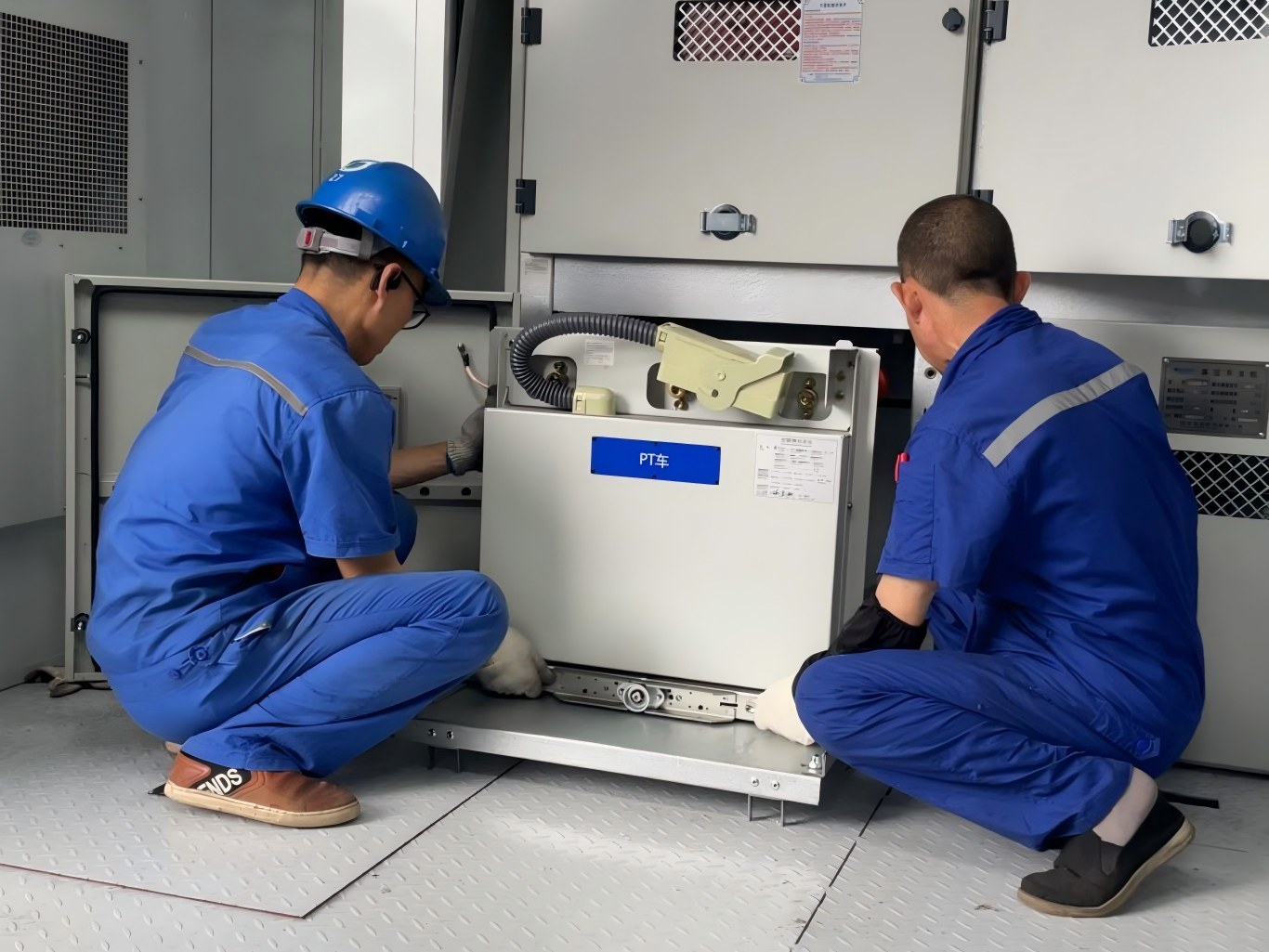
Medium Voltage Switchgear Operation Procedure
Although the design of medium voltage switchgear includes reliable interlocking systems to ensure correct operating sequences, operators must still strictly follow operating procedures and related safety requirements.
Do not operate the equipment randomly. If operation resistance occurs, operators should identify the cause before taking further action. Forced operation may damage the equipment or even cause serious accidents.
Medium Voltage Switchgear Power-On Operation Process
Step 1
Close all cabinet doors and rear cover panels, then lock them securely.
Step 2
Insert the grounding switch operating handle into the hexagonal hole at the lower right side of the middle cabinet door.
Turn the handle counterclockwise approximately 90° to open the grounding switch. Remove the operating handle. The interlocking plate at the operating hole will automatically return and cover the opening, locking the rear door of the switchgear.
Step 3
Check whether all meters and signal indicators on the upper cabinet door are functioning normally.
Under normal conditions:
- The power indicator of the microcomputer protection device should be on.
- The circuit breaker truck test position indicator should be on.
- The circuit breaker open indicator should be on.
- The energy storage indicator should be on.
If none of the indicators are illuminated, open the upper cabinet door and check whether the busbar power switches are closed.
If the switches are closed but the indicators remain off, inspect the control circuit.
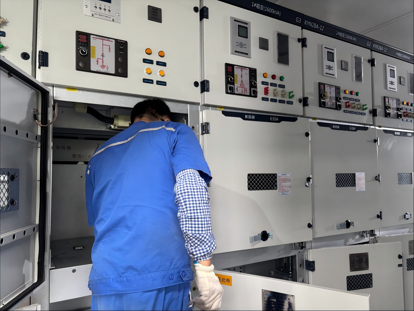
Step 4
Insert the circuit breaker truck operating handle into the operating port and press it firmly downward.
Turn the handle clockwise. When obvious resistance is felt along with a “click” sound, remove the handle.
At this point, the circuit breaker truck has moved to the service position, and the secondary plug is locked.
The main circuit of the circuit breaker is connected. Check the relevant status signals:
- The service position indicator is illuminated.
- The test position indicator is off.
When the circuit breaker truck is in the service position, the interlocking plate at the grounding switch operating hole is locked and cannot be pressed.
Step 5
Operate the closing/opening selector switch on the instrument panel to close the circuit breaker and energize the system.
After successful closing:
- The red closing indicator light turns on.
- The green opening indicator light turns off.
Check the live display device, mechanical position indicator of the circuit breaker, and other related signals.
If everything operates normally, power transmission is completed.
When operating the closing/opening selector switch, rotate the handle clockwise to the closing position shown on the panel. After releasing the handle, it should automatically return to the pre-closing position.
Step 6
If the circuit breaker trips automatically after closing or trips during operation, identify and eliminate the fault cause before repeating the above power-on procedure.
FAQs
1. What is medium voltage switchgear?
Medium voltage switchgear is electrical equipment that manages power systems with voltage levels from 3kV to 40.5kV. It receives, distributes, controls, and protects electrical energy through integrated components such as circuit breakers, disconnect switches, and protection devices.
2. What are the main types of medium voltage switchgear?
Medium voltage switchgear has different types based on structure, circuit breaker installation, and insulation technology. Common types include armored switchgear, compartment switchgear, box-type switchgear, air insulated switchgear, and SF₆ gas insulated switchgear.
3. Where do we use medium voltage switchgear?
Medium voltage switchgear plays an important role in industrial power distribution systems, renewable energy projects, power plants, substations, commercial buildings, and distribution networks. It helps control power flow, protect electrical equipment, and isolate faults.
4. What is KYN medium voltage switchgear?
KYN medium voltage switchgear is a metal-clad withdrawable switchgear solution for three-phase AC power systems from 3kV to 40.5kV. It supports electrical energy distribution, circuit control, protection, and fault isolation in power plants, substations, and industrial facilities.
5. What are the main components of medium voltage switchgear?
The main components of medium voltage switchgear include the cabinet body, circuit breaker compartment, busbar compartment, cable compartment, relay and instrument compartment, protection devices, and grounding system. Together, these components ensure safe and reliable power distribution.
Conclusion
Medium voltage switchgear is a critical component in power distribution systems, performing essential functions such as electrical energy distribution, control, and fault protection.
Understanding medium voltage switchgear types, components, and operation procedures helps engineers select safer and more reliable power distribution solutions according to project requirements.
Since medium voltage switchgear directly affects the stability and safety of power systems, product design, manufacturing processes, and quality control are extremely important.
Wondon specializes in the research, development, and manufacturing of medium voltage switchgear and complete electrical equipment. We provide customized solutions for industrial, renewable energy, and power projects, offering one-stop services covering system design, manufacturing, and technical support.
If you are looking for a reliable medium voltage switchgear solution, please feel free to contact us. Our professional team can provide product selection recommendations and technical support based on your project requirements.