

A medium voltage switchgear design guide that starts with a switchgear catalog is already going the wrong direction. Start with the power system: voltage, load, fault current, grounding method, protection strategy, installation environment, and what the site will need five years from now.
Reliable MV power distribution is not the result of one high-rated component. It comes from matching all of those factors to each other.
Here are the design factors in the order they actually come up on a project. If you are an EPC contractor, electrical engineer, consultant, or buyer, use this as a working checklist for a more complete MV switchgear specification and RFQ.
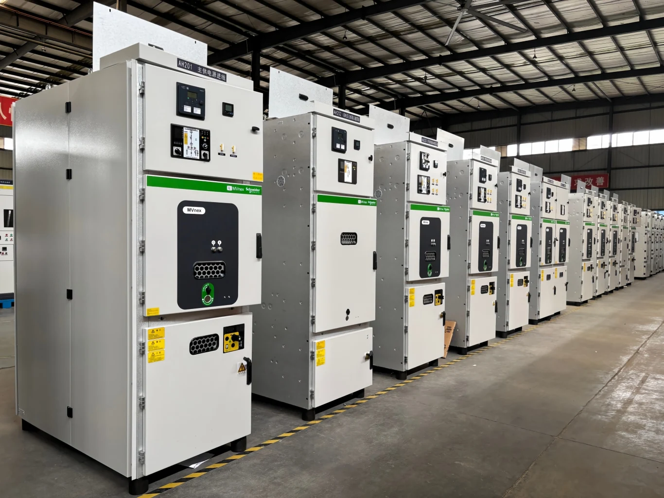
1. Start With the Power System, Not the Switchgear
Before anyone debates enclosure type or breaker brand, define the electrical system.
At minimum: system voltage, frequency, normal load current, maximum and minimum short-circuit current, short-circuit duration, grounding method, and installation conditions.
Get these wrong and everything downstream is wrong. Busbar sizing, CT ratios, relay settings, cable terminations, the lot. IEC 62271-200 gives you the framework for AC metal-enclosed switchgear: ratings, internal arc classification, service continuity, partitioning.
The design inputs, and why each one matters:
| Design input | Why it matters |
|---|---|
| System voltage | Determines equipment voltage class and insulation requirements |
| Frequency | Determines compatibility with the power system |
| Continuous load current | Determines continuous current rating |
| Maximum fault current | Determines fault withstand and interrupting requirements |
| Minimum fault current | Helps verify protection sensitivity |
| Grounding method | Influences earth-fault current and protection |
| Ambient temperature | Can affect thermal performance and derating |
| Altitude | Can affect insulation and cooling |
| Installation environment | Influences enclosure and environmental protection |
That table is the reason a 12 kV, 24 kV, or 36 kV lineup cannot be chosen on “it matches the system voltage” alone.
2. Define MV Switchgear Ratings Correctly
Now translate the system conditions into equipment ratings.
Rated Voltage and Insulation Level
Rated voltage sets the voltage class of the equipment. It does not by itself set the insulation design. That also depends on power-frequency withstand voltage and lightning impulse withstand voltage.
A typical MV switchgear specification lists both, because they cover different events: sustained overvoltage and transient overvoltage.
Which values you need comes from the system and the applicable standard. Voltage alone will not tell you.
Rated Current
Rated continuous current has to cover expected operating load, plus whatever you are about to add.
A feeder carrying 700 A today is a different problem if transformers, motors, production lines, or PV come online in two years.
Both mistakes cost money. Undersizing buys you a rebuild. Oversizing buys you a bigger invoice and a worse power factor of spend.
3. Check Both Maximum and Minimum Short-Circuit Current
Short-circuit rating is where MV switchgear design quietly goes wrong, because most people stop at one number.
Maximum short-circuit current tells you whether the breaker and busbar can withstand and interrupt the fault. That means short-time withstand current, peak withstand current, and interrupting capability. Manufacturer design guides normally list these next to continuous current and insulation level.
Minimum short-circuit current asks something else entirely: can the protection actually see the fault?
A fault at the far end of a long feeder produces far less current than a fault at the busbar. Set the relay pickup too high and it will not trip. This is the case that gets missed.
Run both:
Maximum fault current → equipment withstand and interruption
Minimum fault current → protection sensitivity and fault clearing
4. Consider the System Grounding Method Early
Grounding gets less attention than voltage and current during equipment selection. It reaches further than most people expect.
Solid, resistance, reactance, or ungrounded: the choice sets the magnitude and shape of earth-fault current. From there it drives protection settings, CT selection, surge arrester requirements, cable shield grounding, and insulation coordination.
Eaton’s MV design material shows surge arrester selection varying with the grounding method, and notes how temperature inside outdoor switchgear affects arrester application.
Fix the grounding method before you finalize the protection scheme or lock in major equipment ratings.
5. Choose the Right MV Switchgear Configuration
Only now do you compare configurations. Air-insulated (AIS), gas-insulated (GIS), metal-clad, metal-enclosed, fixed breaker, withdrawable breaker.
There is no universal answer here. There is a right answer for your project.
AIS vs GIS
AIS is familiar, accessible, and easy to work on. GIS earns its price when floor space is tight or when the environment is hostile enough to need a sealed solution.
Modern MV GIS units put high voltage ratings, short-circuit ratings, internal arc classification, and a small footprint into one assembly.
Compare past the purchase price: footprint, maintenance access, site conditions, installation requirements, expansion room, lifecycle cost.
Fixed vs Withdrawable Circuit Breakers
Fixed breakers are simpler and take less space.
Withdrawable breakers let you rack the breaker out of the primary circuit for inspection, testing, replacement, or maintenance without tearing down the whole lineup.
Where maintenance is frequent or continuity requirements are strict, that difference pays for itself.
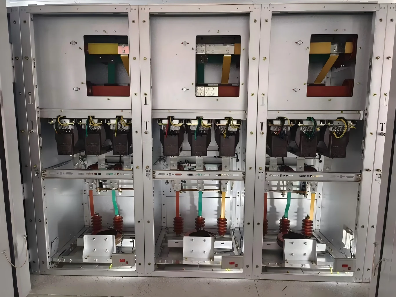
6. Design Protection and Fault-Clearing as One System
A breaker on its own is not a protection strategy.
A working MV protection system is breakers, CTs, VTs, relays, upstream protection, downstream protection, and the communication between them.
Two things have to be true. The breaker has to interrupt the fault. The protection system has to find the right fault and isolate the smallest possible section.
Most specifications only ever test the first one.
Coordination is what keeps one fault from taking out the whole plant. CT performance matters here too. A saturated CT sends the relay a signal that does not describe the fault in front of it.
Define protection requirements together with the primary equipment. Treat them as separate packages and you get a lineup that is technically fine and operationally awkward.
7. Design Internal Arc Protection With the Room Layout
A product specification can give you false confidence on internal arc.
IEC 62271-200 covers internal arc classification (IAC), including test conditions and criteria for the relevant assemblies. You will see IAC AFL or IAC AFLR in MV switchgear specifications, describing which accessible sides were tested and under what conditions. Siemens, for example, lists IAC classifications alongside its IEC 62271-200-based MV switchgear designs.
Now the part no datasheet answers. What happens to that classification once the lineup is sitting in your actual substation room?
Pressure relief direction, release ducts, room layout, accessible sides, doors, walls, maintenance routes. Every one of them changes the real installation.
So design internal arc protection as a switchgear-and-room system. Write “arc-resistant” in an RFQ, assume the installed arrangement satisfies the safety requirement, and you leave a gap that factory tests will never catch.
8. Design for Real Site Conditions, Not Standard Conditions
Standard laboratory conditions describe almost no project site.
Temperature, altitude, humidity, condensation, dust, salt mist, corrosive gases, vibration, seismic. All of it lands on MV switchgear design.
Temperature and Solar Radiation
High ambient temperature eats your thermal margin. Outdoors there is a second problem: solar radiation pushes the internal temperature above the surrounding air temperature. Eaton notes this specifically for outdoor metal-enclosed switchgear.
That matters when you pick surge arresters and when you verify current-carrying capability.
Humidity and Condensation
High humidity plus a large day-night swing is the standard tropical problem.
Water does not have to enter the enclosure. Condensation on its own is enough to create insulation and corrosion risk.
Depending on the site, you may need anti-condensation heaters, ventilation, tighter sealing, or other environmental controls.
Dust and Salt
Mining, coastal, desert, chemical. Enclosure design and insulation surfaces need more attention than a standard indoor unit gets.
For these projects, “indoor” or “outdoor” does not describe the environment well enough.
9. Design the Enclosure, Access and Installation Space
A technically correct switchgear lineup is still a problem if it does not fit the building.
Before you freeze the design, check:
- Cable entry and termination space
- Front and rear access
- Maintenance clearance
- Door opening space
- Breaker withdrawal path
- Busbar arrangement
- Room dimensions
- Pressure relief path
- Transportation and lifting route
Retrofit projects are where this bites hardest. You can have all the electrical capacity you need and still have no practical route to get a replacement breaker into the room.
Honestly, physical installation conditions belong in the design before manufacturing starts. Not after the truck arrives.
10. Plan Retrofit and Future Expansion Before Manufacturing
Existing substations come with constraints attached.
Replacing or adding MV switchgear means matching what is already there: busbar interface, phase sequence, cable termination, foundation, control voltage, secondary terminals, protection settings, interlocking logic.
Then there is SCADA.
Plan the expansion at the same time. Extra feeders later means spare panel positions, busbar capacity, protection coordination, physical extension space, control-system capacity. Decide now, while the drawing is still open.
A “modular” switchgear design only helps if the future expansion actually matches the original electrical and mechanical architecture.
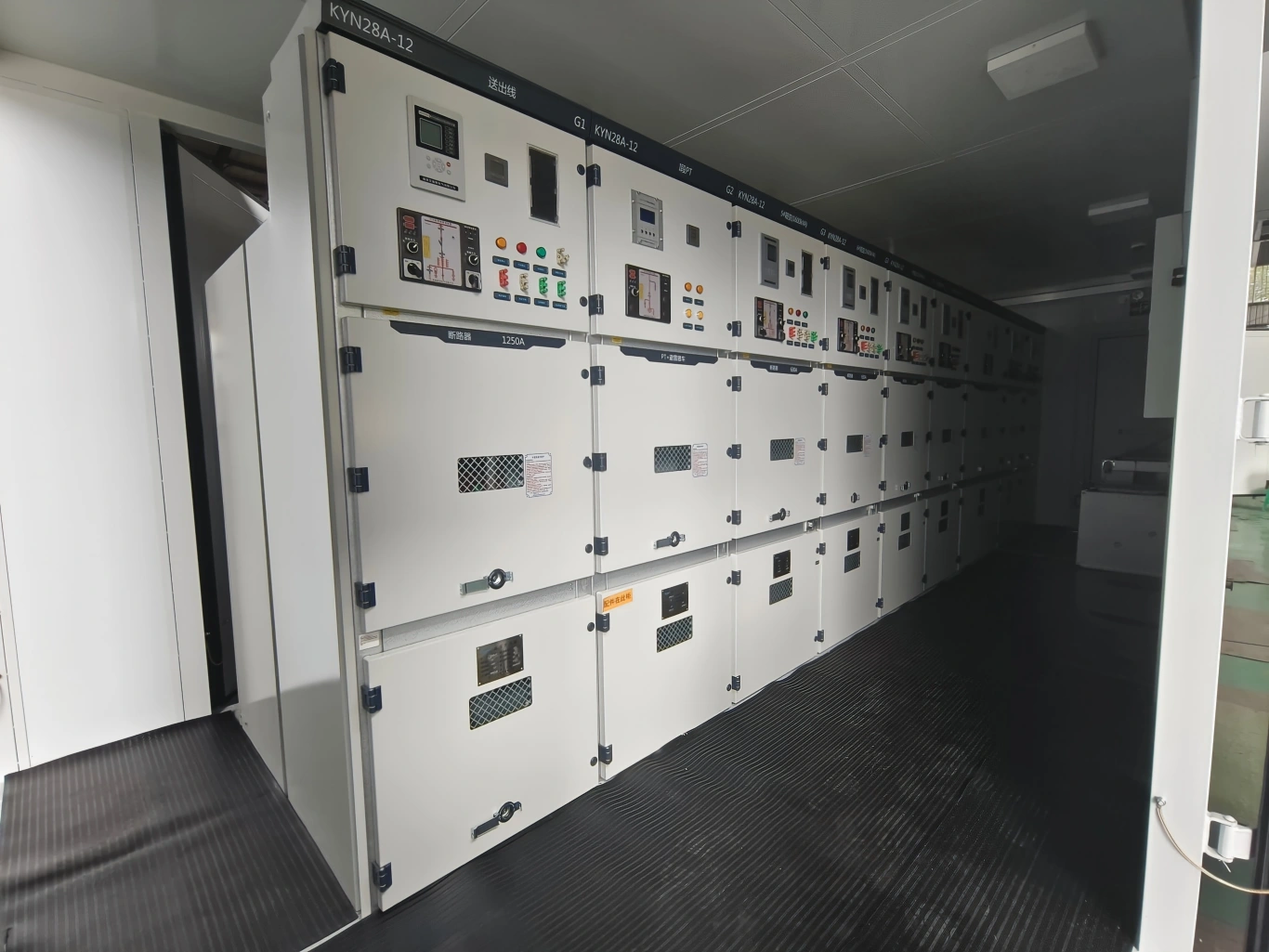
11. Make Digital Monitoring Part of the Design
Do not start by asking which smart sensor to buy. Start with what you need to know.
Current, voltage, power, breaker operation, temperature, partial discharge, alarms, protection events. Keep the ones that will change somebody’s decision.
Then define the path:
Sensor → relay or IED → communication gateway → SCADA/EMS → alarm → maintenance action
That sequence prevents the usual outcome: a room full of sensors and nobody looking at the data.
Also settle the communication protocols, alarm thresholds, network segmentation, and what happens when a sensor or the comms link dies.
12. Design for Maintenance and Lifecycle Reliability
Reliability does not stop when the unit passes factory tests.
Ask how it behaves at year five, year ten, year fifteen. Breaker replacement, inspection access, test interfaces, spare parts, relay upgrades, partial discharge testing, and whether the local maintenance team can actually do the work.
A design that needs a specialist for every minor intervention runs expensive for the next fifteen years. In B2B projects, maintainability is a line in the technical specification, not an after-sales topic.
13. Consider the Full Lifecycle When Choosing Switching Technology
Vacuum switching, air insulation, clean-air solutions, solid insulation, gas insulation. All of them have a place in MV.
Price and environmental positioning are not enough to decide between them. Compare:
- Required footprint
- Insulation requirements
- Operating temperature
- Maintenance strategy
- Environmental conditions
- Applicable regulations
- Service requirements
- Lifecycle considerations
A compact solution earns its keep where space is scarce. A more accessible arrangement is easier to live with in a large industrial facility. Which one you need depends on the project, not on the brochure.
14. Check Applicable Standards Before Finalizing the Design
IEC 62271-200 covers AC metal-enclosed switchgear, including internal arc classification, loss of service continuity, and partitioning. The current edition is 2021, with later amendments listed by IEC.
Depending on the project you may also be working to other IEC standards, local grid codes, utility specifications, and national requirements.
“IEC compliant” is not a technical specification. Your RFQ should name the applicable standards, ratings, testing requirements, environmental conditions, protection requirements, and documentation.
15. Medium Voltage Switchgear Design Checklist
Before you approve an MV switchgear design, check the following:
Electrical system
- System voltage and frequency
- Continuous load current
- Maximum short-circuit current
- Minimum fault current
- Short-circuit duration
- Grounding method
Switchgear
- Rated voltage
- Rated current
- Insulation level
- Short-time withstand current
- Peak withstand current
- Breaking capacity
- AIS or GIS
- Fixed or withdrawable breaker
Protection
- CT and VT requirements
- Protection relay
- Earth-fault protection
- Protection coordination
- Interlocking
- Control and communication
Site conditions
- Ambient temperature
- Altitude
- Humidity
- Condensation
- Dust
- Salt mist
- Corrosive atmosphere
- Seismic requirements
Installation and maintenance
- Cable entry
- Room dimensions
- Access clearance
- Internal arc pressure relief
- Maintenance space
- Breaker replacement route
- Future expansion
A Practical Way to Approach MV Switchgear Design
For a new project, work the design in this order:
System requirements → fault study → grounding → protection → insulation → switchgear configuration → internal arc safety → site conditions → installation → monitoring → maintenance → future expansion
Each step constrains the next one. Skip ahead and you will redo the fault study after the vendor is already selected.
The short version: reliable MV power distribution comes from designing the switchgear, protection system, installation environment, and maintenance strategy as one system.
Frequently Asked Questions About MV Switchgear Design
1. What should be considered when designing medium voltage switchgear?
Key factors include system voltage, rated current, short-circuit current, grounding method, insulation level, protection coordination, internal arc protection, environmental conditions, installation space, and future expansion.
2. How do you determine the short-circuit rating of MV switchgear?
Start with a short-circuit study to determine the maximum fault current. Then verify the switchgear’s short-time withstand current, peak withstand current, and circuit breaker interrupting capacity. The minimum fault current should also be checked for protection sensitivity.
3. How does grounding affect MV switchgear design?
The grounding method affects earth-fault current, protection settings, CT requirements, surge arrester selection, and insulation coordination. It should therefore be defined early in the design process.
4. What is IAC in medium voltage switchgear?
IAC means Internal Arc Classification. It describes how switchgear performs under specified internal arc test conditions. The tested configuration, accessible sides, fault current, duration, and pressure-relief arrangement should match the actual installation requirements.
5. How do I choose between AIS and GIS?
Consider space, environmental conditions, maintenance access, installation requirements, project cost, and lifecycle needs. AIS suits many conventional applications, while GIS can offer a more compact solution where space or environmental protection is important.
6. What information should I provide for an MV switchgear quotation?
Provide the system voltage, frequency, rated current, short-circuit level, grounding method, feeder requirements, protection requirements, installation environment, applicable standards, and cable arrangement. A single-line diagram and project specification can further improve the technical review.
Need Help Defining Your MV Switchgear Specification?
If you already have a single-line diagram, load list, short-circuit data, or a project specification, send it over. Our electrical engineering team will review the key technical inputs and provide the MV switchgear ratings, configuration, protection requirements, environmental conditions, and customization options that fit the project.
You do not need a complete drawing yet. Voltage, current, short-circuit level, installation environment, and the application are enough to start the conversation.