

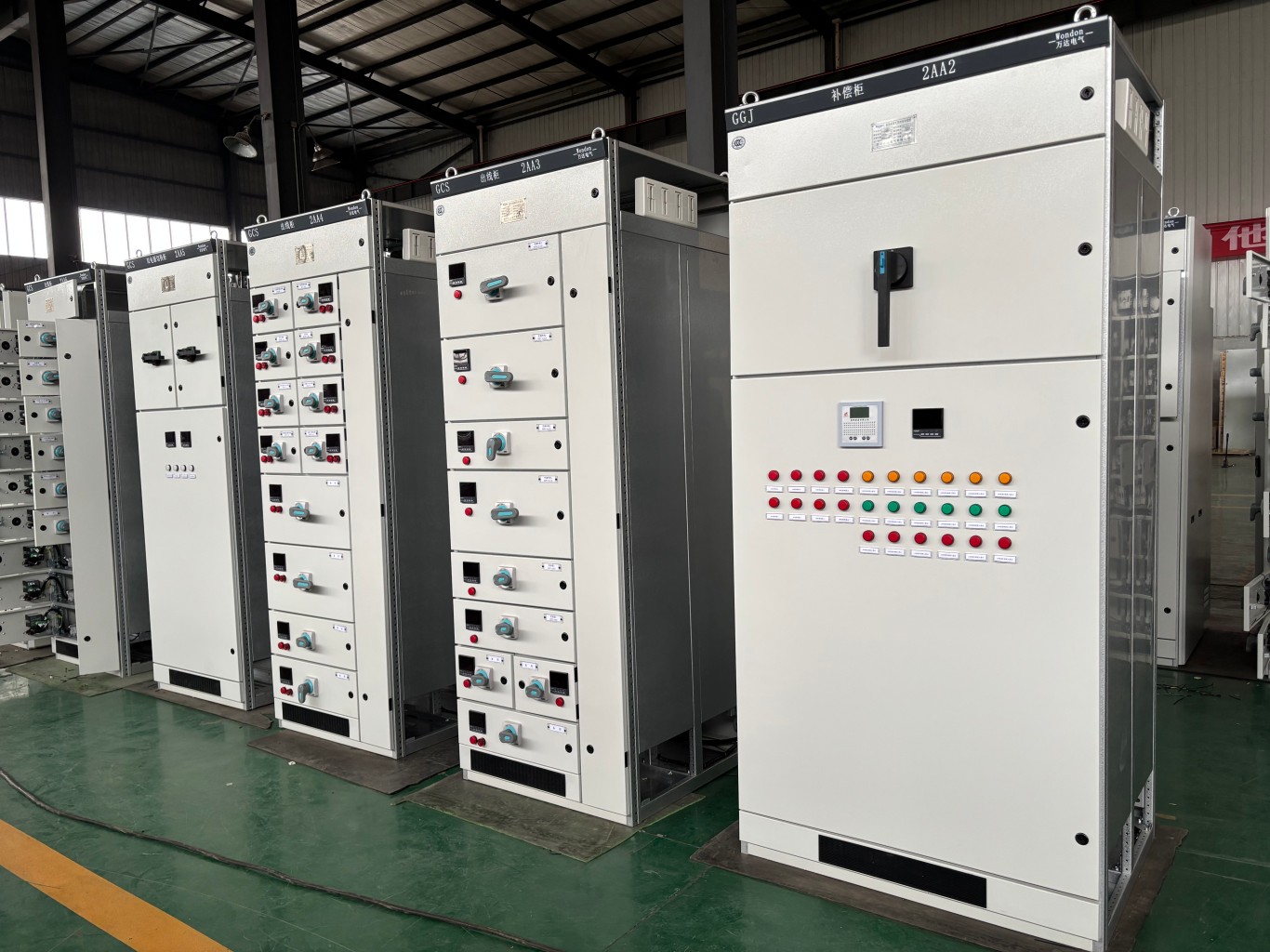
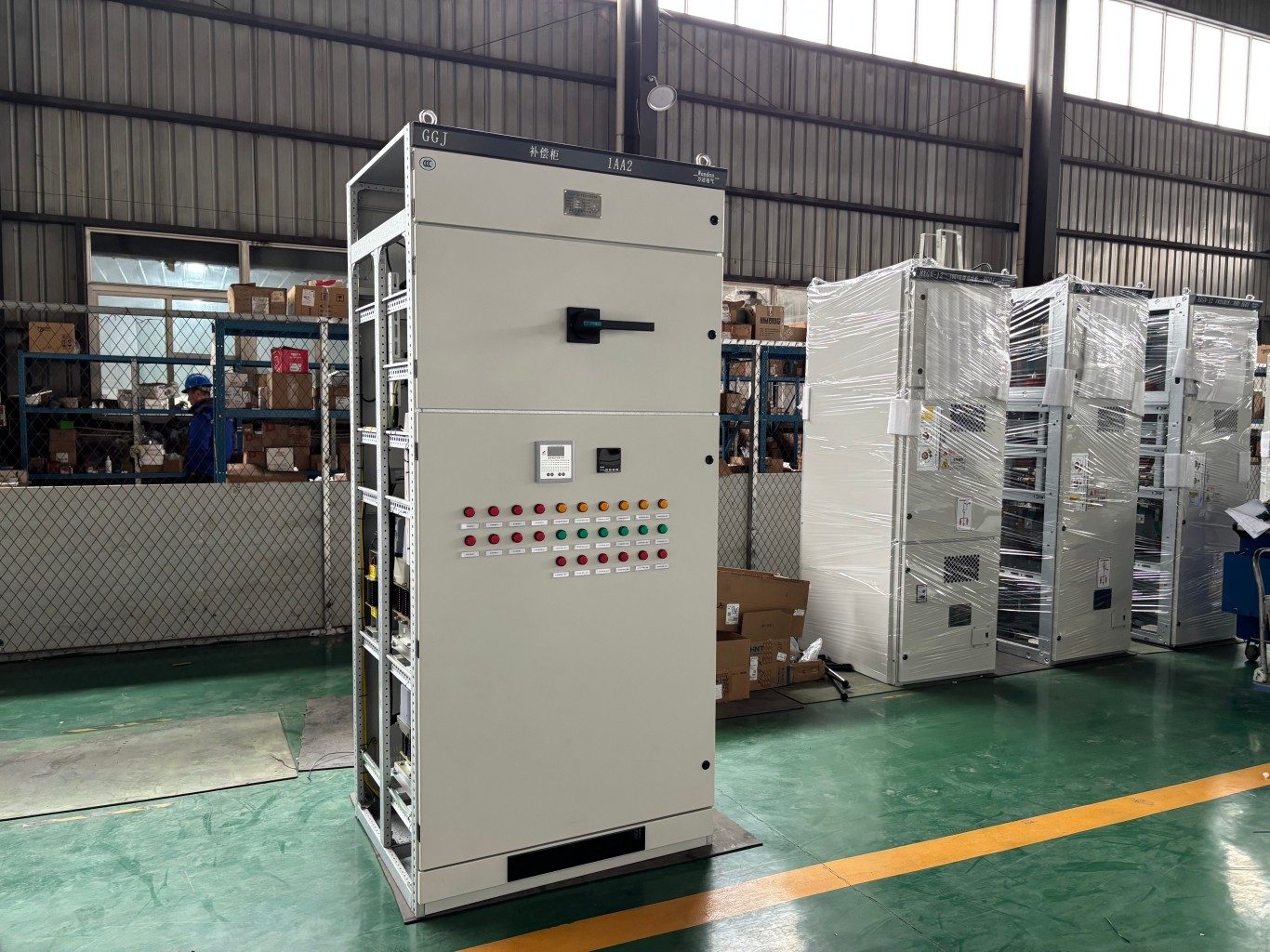
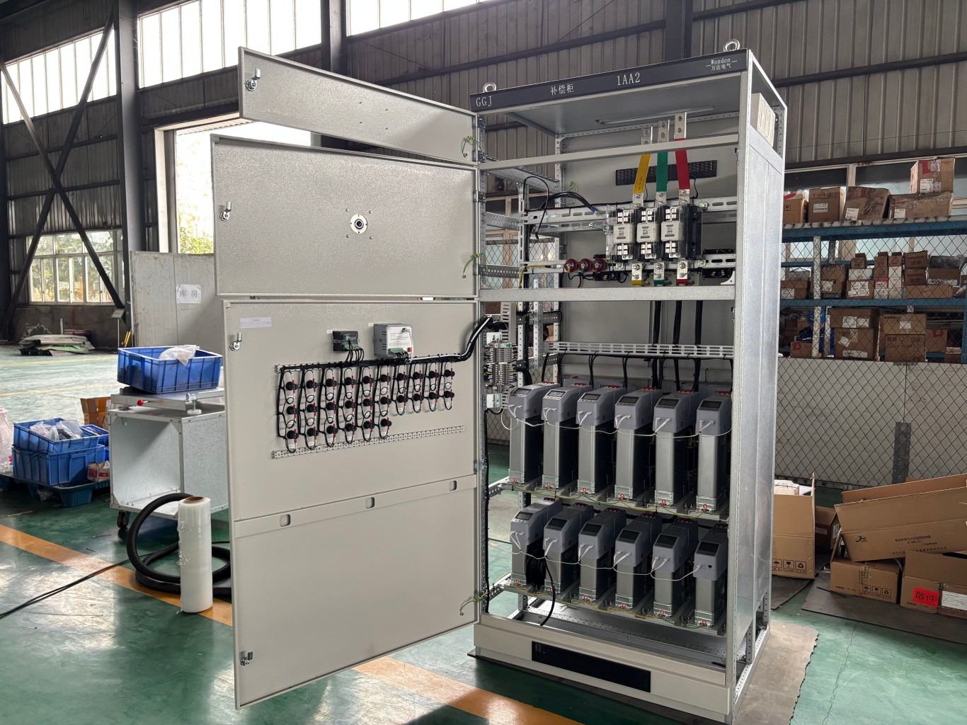
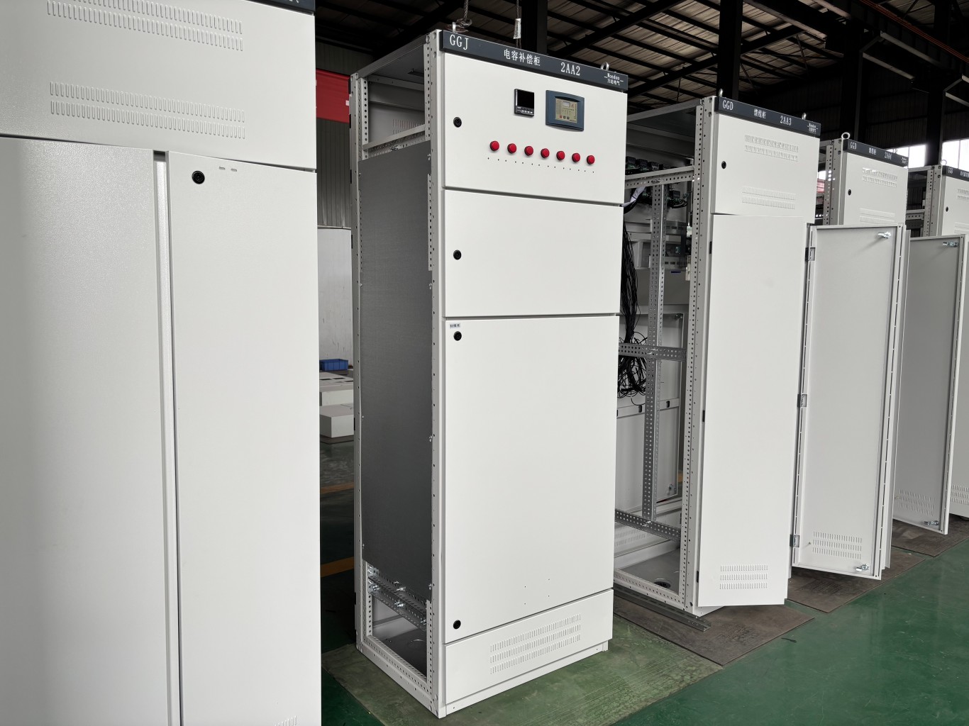
A low voltage switchgear lineup typically includes incoming feeder cabinets and outgoing feeder cabinets. Of course, a capacitor compensation cabinet also plays an important role in the lineup. As its name suggests, the capacitor compensation cabinet provides capacitor compensation for the power distribution system.
Have you ever wondered why low voltage switchgear needs capacitor compensation? In this article, I will explain the principle, advantages and disadvantages, compensation methods, capacity calculation, and safe operation requirements of capacitor compensation.
Power Capacitor Compensation Principle
Let’s first take a look at how capacitor compensation works.
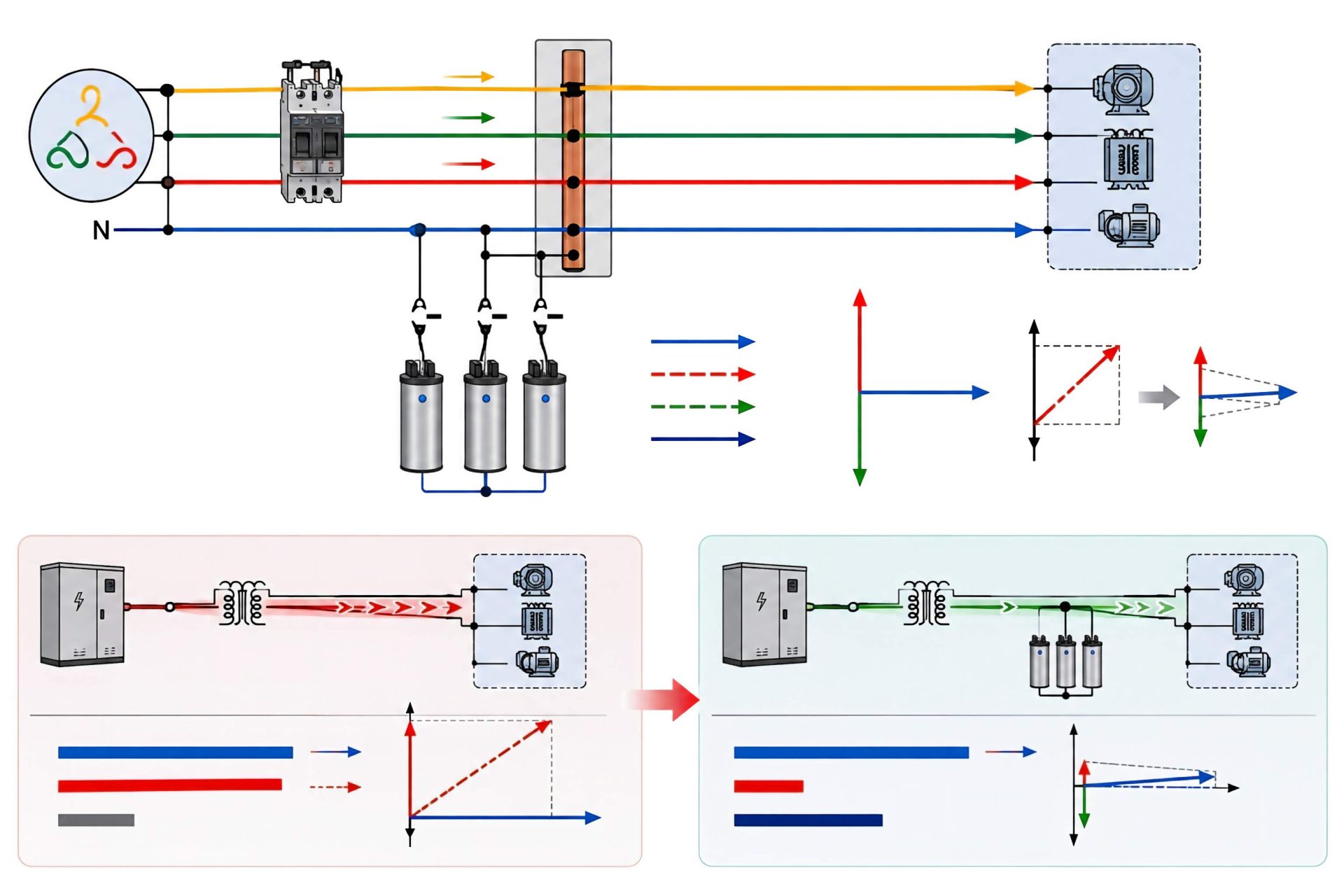
During capacitor compensation, the capacitor connects in parallel with the load. You can think of a capacitor as an energy storage device. When the load increases, the internal resistance of the power supply causes its output voltage to drop. Because the capacitor tends to maintain the voltage across its terminals, it releases part of its stored energy and helps slow down the voltage drop. This is the basic principle of capacitor compensation.
In principle, a power capacitor acts like a generator that provides capacitive reactive current. The principle of reactive power compensation is to connect capacitive loads and inductive loads in parallel within the same power system, allowing energy to exchange between the two types of loads.
As a result, the load on transformers and transmission lines in the power grid decreases, while the system’s ability to deliver active power increases. At the same active power output, the power supply system can also reduce its losses.
Power capacitors provide one of the simplest and most economical ways to reduce the load on transformers, power supply systems, and industrial distribution systems. Therefore, capacitor compensation has become an important part of reactive power compensation in power systems. Today, engineers widely use parallel capacitors as reactive power compensation equipment.
Features of Power Capacitor Compensation
Advantages
Power capacitor reactive power compensation systems offer several practical advantages:
- Easy installation and flexible adjustment of the installation location.
- Low active power loss, typically around 0.4% of the rated capacity.
- Short construction period.
- Low investment cost.
- No rotating components, making operation and maintenance relatively simple.
- If an individual capacitor unit fails, the remaining capacitor units can continue operating.
Disadvantages
However, capacitor compensation also has some limitations:
- It only provides stepwise adjustment and cannot achieve smooth continuous adjustment.
- Poor ventilation can cause the capacitor temperature to rise. When the operating temperature exceeds 70°C, the capacitor may expand or even explode.
- Its voltage characteristics are relatively poor, and it has limited short-circuit stability. After disconnection, residual charge may remain in the capacitor.
- The reactive power compensation accuracy is relatively low, which may affect the overall compensation performance.
- Operation and management of compensation capacitors can be difficult, and capacitor safety may not always receive sufficient attention.
Reactive Power Compensation Methods
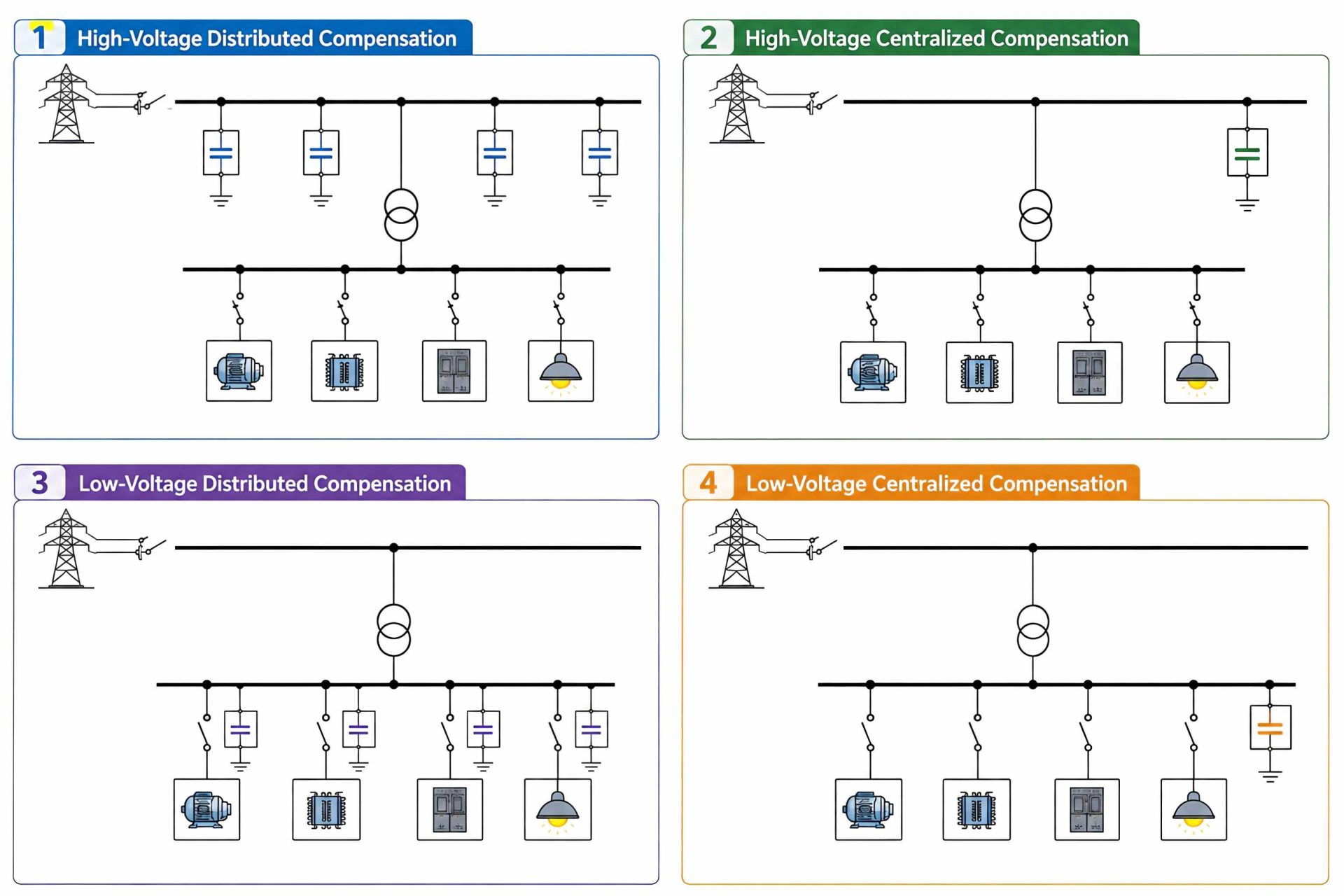
High-Voltage Distributed Compensation
High-voltage distributed compensation refers to installing reactive power compensation capacitors on the high-voltage side of an individual transformer to improve power supply voltage quality. This method mainly applies to high-voltage urban power distribution systems.
High-Voltage Centralized Compensation
High-voltage centralized compensation refers to installing capacitors on the 6 kV–10 kV high-voltage busbar of a substation or a user’s step-down substation.
Engineers can also install capacitors on the low-voltage busbar in the user’s main distribution room. This method suits sites with relatively concentrated loads, locations close to the distribution busbar, and applications that require a relatively large compensation capacity. When the user also has a certain amount of high-voltage load, this method can reduce reactive power consumption from the power system and provide effective compensation.
The main advantages include easy automatic switching, improved user power factor, high utilization, relatively low investment, convenient maintenance, and flexible adjustment. It can also help prevent overcompensation and improve voltage quality.
The main disadvantage is that this compensation method provides relatively poor economic benefits.
Low-Voltage Distributed Compensation
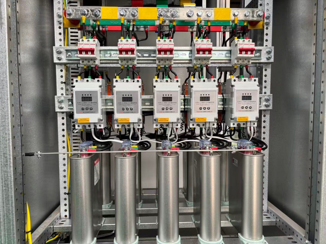
Low-voltage distributed compensation means installing one or more low-voltage capacitor banks near individual electrical loads according to their reactive power requirements. This arrangement compensates for the reactive power of all high- and low-voltage lines and transformers upstream of the installation point.
The main advantage is that the capacitor compensation equipment operates together with the electrical load. When the electrical equipment operates, the reactive power compensation system switches into operation. When the equipment stops, the compensation equipment also disconnects.
This arrangement reduces reactive power flow through the distribution network and transformers, thereby reducing active power losses. It can also reduce the required conductor cross-sectional area and transformer capacity while occupying relatively little space.
However, this method has a relatively low utilization rate and requires higher investment. It is also unsuitable for motors operating under variable speed, forward and reverse operation, inching, locked-rotor conditions, or plugging braking.

Low-Voltage Centralized Compensation
Low-voltage centralized compensation connects low-voltage capacitors to the low-voltage side of a distribution transformer through a low-voltage switch. A reactive power compensation switching device acts as the control and protection device and directly controls capacitor switching according to the reactive power load on the low-voltage busbar.
The capacitors switch as complete groups, so the system cannot achieve smooth continuous adjustment.
The main advantages of low-voltage centralized compensation include simple wiring and a relatively low operation and maintenance workload. It balances reactive power locally, improves distribution transformer utilization, and reduces network losses. Therefore, it provides good economic benefits and remains one of the most commonly used reactive power compensation methods.
Calculation of Capacitor Compensation Capacity
The required reactive power compensation capacity should be determined according to the reactive power curve or an appropriate reactive power compensation calculation method.
The calculation formula is:
Qc = P(tanφ₁ − tanφ₂)
or:
Qc = P × qc
Where:
- Qc: Capacitor compensation capacity
- P: Active load power
- cosφ₁: Load power factor before compensation
- cosφ₂: Load power factor after compensation
- qc: Reactive power compensation rate, in kvar/kW
Safe Operation of Power Capacitors
1. Allowable Operating Current
During normal operation, the capacitor should operate at its rated current. The maximum operating current should not exceed 1.3 times the rated current, and the difference between the three-phase currents should not exceed 5%.
2. Allowable Operating Voltage
Capacitors are highly sensitive to voltage because capacitor losses increase in proportion to the square of the voltage. Overvoltage can cause excessive heating, accelerate insulation aging, shorten the service life of the capacitor, and may even cause electrical breakdown.
Therefore, the capacitor system should operate at its rated voltage. Under normal conditions, the operating voltage should generally not exceed 1.05 times the rated voltage, while the maximum operating voltage should not exceed 1.1 times the rated voltage.
When the busbar voltage exceeds 1.1 times the rated voltage, take appropriate cooling measures.
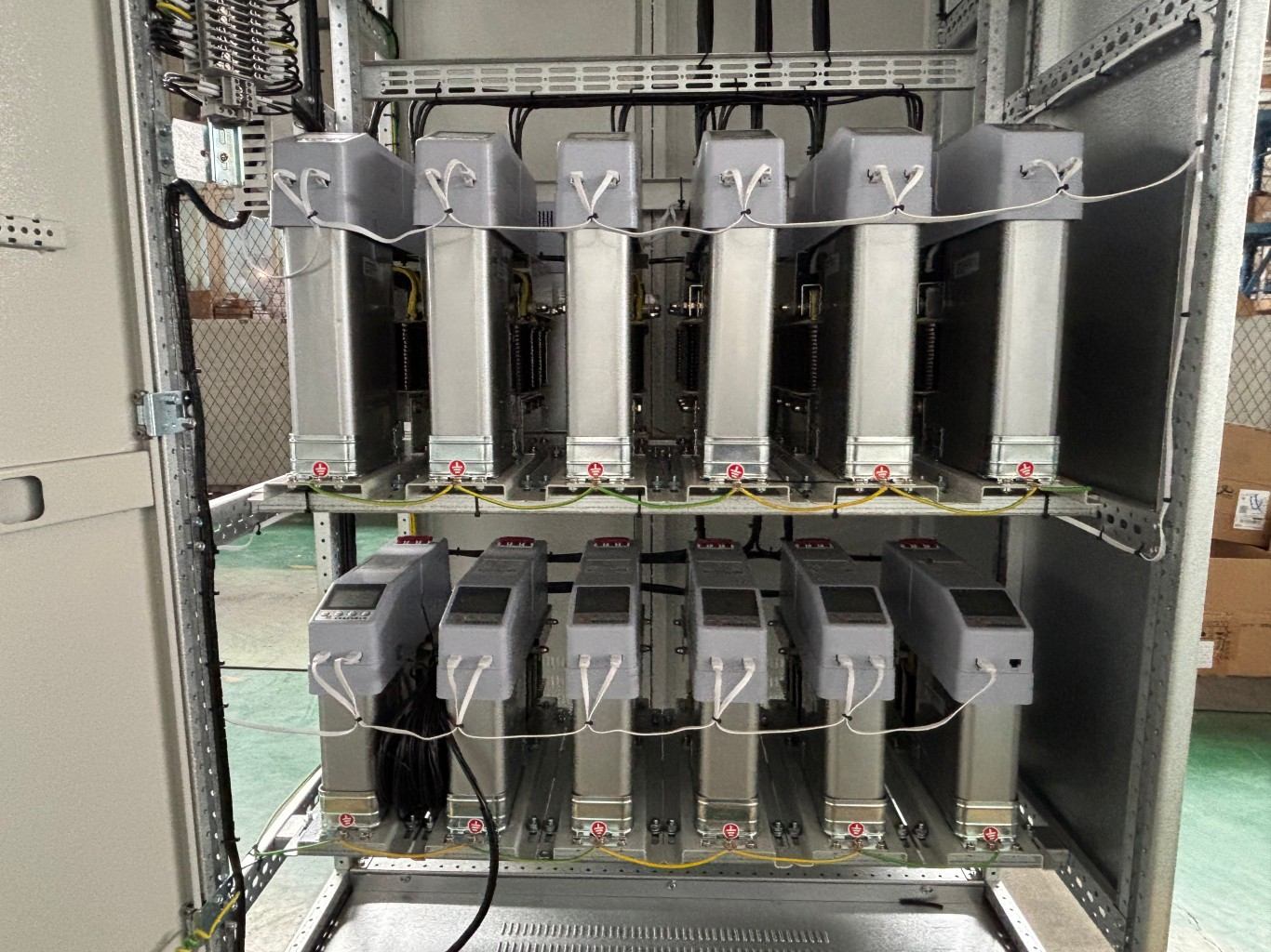
3. Harmonic Problems
A capacitor circuit forms an LC circuit. Therefore, it can resonate with certain harmonics, which may increase high-order harmonics, current, and voltage.
Harmonic currents can seriously damage capacitors and may easily cause capacitor breakdown, resulting in phase-to-phase short circuits.
Therefore, when necessary, install a reactor with an appropriate inductive reactance value in series with the capacitor to limit harmonic currents during normal capacitor operation.
4. Relay Protection
Relay protection mainly relies on integrated relay protection equipment. Several well-known electrical manufacturers currently produce mature relay protection systems with reliable operation, stable performance, and comprehensive functions.
Relay protection devices can effectively disconnect faulty capacitors and provide an important means of maintaining the safe and stable operation of the power system.
The main relay protection measures for capacitors include:
- Three-stage overcurrent protection.
- Overvoltage protection to prevent capacitor damage caused by steady-state system overvoltage.
- Undervoltage protection to prevent overvoltage damage caused by instantaneous reclosing of capacitors following a short-term power interruption.
- Unbalanced voltage protection, unbalanced current protection, or three-phase differential voltage protection to detect internal breakdown faults within a capacitor bank.

5. Reclosing
Capacitor banks must not undergo reclosing while charged.
The main reason is that capacitors require a certain amount of time to discharge. After the capacitor bank trips, immediate reclosing may occur before the capacitor has fully discharged. Residual charge with a polarity opposite to the reclosing voltage may remain in the capacitor.
This condition can generate a very high inrush current at the moment of reclosing, potentially causing the capacitor enclosure to expand, oil to spray out, or even an explosion.
Therefore, when reclosing a capacitor bank, wait at least 3 minutes after the circuit breaker opens.
For this reason, engineers should not install automatic reclosing devices for capacitor banks. Instead, they should install an automatic trip device with no-voltage release.
Some terminal substations use automatic standby power switching devices. When the main power supply fails, the device disconnects the faulty power source and then connects the standby power supply after a short delay.
If the capacitor bank has an automatic undervoltage switching function, it may reconnect within a short period during this process. This can create the fault conditions described above.
Therefore, systems equipped with automatic standby power switching devices require particular attention to the switching control of capacitor banks.
6. Allowable Operating Temperature
During normal operation, the rated ambient temperature around the capacitor is generally -25 °C to 40 °C.
The temperature of the internal dielectric should remain below 65°C and must not exceed 70°C. Otherwise, thermal breakdown or capacitor bulging may occur.
The temperature of the capacitor enclosure falls between the dielectric temperature and the ambient temperature and should not exceed 55°C.
Therefore, maintain good ventilation in the capacitor room and ensure that the operating temperature remains within the allowable range.
7. Discharge Noise During Operation
Under normal operating conditions, capacitors generally operate without producing noticeable noise. However, discharge noise may occur under certain conditions.
For example, if the capacitor bushing remains exposed outdoors for an extended period, rainwater may enter between the two layers of the bushing. Once voltage is applied, this may cause discharge noise.
When the capacitor lacks oil, the lower end of the bushing may become exposed above the oil level, which can also produce discharge noise.
If the capacitor contains a cold solder joint or a disconnected solder joint, flashover discharge may occur inside the oil.
In addition, poor contact between the capacitor core and enclosure can create floating voltage and cause discharge noise.
If any of these conditions occur, take the appropriate corrective action:
- Shut down and discharge the capacitor, remove the outer bushing, dry it thoroughly, and reinstall it.
- Add capacitor oil of the same specification.
- If the discharge noise continues, disassemble the capacitor for inspection and repair.
- Shut down and discharge the capacitor, then correct the connection between the capacitor core and enclosure to ensure proper contact.
8. Explosion Problems
During operation, capacitor damage or explosion may occur under conditions such as internal component breakdown, insulation failure between the capacitor and enclosure, poor sealing, oil leakage, bulging, internal partial discharge, reclosing. In contrast, the capacitor remains charged, excessive temperature, poor ventilation, excessive operating voltage, excessive harmonic content, or switching overvoltage.
To prevent capacitor explosion accidents, take the following measures under normal operating conditions:
- Select fast-acting fuses according to the current flowing through each phase of the capacitor bank, typically at 1.5 to 2 times the corresponding operating current. If a capacitor breaks down, the fuse will melt and disconnect the power supply, preventing the faulty capacitor from generating additional heat.
- Install an ammeter on each phase of the capacitor compensation cabinet and ensure that the difference between the phase currents does not exceed ±5%. If an imbalance occurs,
- immediately disconnect the capacitor bank from operation and inspect the capacitors.
- Monitor the temperature rise of the capacitors during operation.
- Strengthen routine inspections of capacitor banks and check for oil leakage or bulging to reduce the risk of explosion.
FAQs
1. Why is capacitor compensation needed in low voltage switchgear?
Capacitor compensation reduces reactive power, improves power factor, lowers power losses, and increases the efficiency of low voltage power distribution systems.
2. What does a capacitor compensation cabinet do?
A capacitor compensation cabinet automatically switches capacitor banks to provide reactive power compensation, improve power factor, reduce reactive current, and optimize power distribution.
3. How do you calculate capacitor compensation capacity?
You can calculate capacitor compensation capacity using Qc = P(tanφ₁ − tanφ₂), where P is active power and φ₁ and φ₂ represent the power factor angles before and after compensation.
4. What are the main types of capacitor compensation?
The main types include high-voltage distributed compensation, high-voltage centralized compensation, low-voltage distributed compensation, and low-voltage centralized compensation.
5. What should you consider when selecting a capacitor compensation system?
Consider the load profile, required compensation capacity, target power factor, operating voltage, harmonics, temperature, switching method, and protection requirements.
Conclusion
Capacitor compensation plays an important role in improving power quality and reducing reactive power losses in low voltage power distribution systems. By selecting the right compensation method and capacity, you can improve power factor, reduce transformer and line losses, and increase the overall efficiency of your electrical system. Proper protection, ventilation, temperature control, and harmonic management also help ensure reliable capacitor operation.
If you are selecting a capacitor compensation cabinet for your low voltage switchgear or need help calculating the required compensation capacity, contact our electrical engineers for a customized capacitor compensation solution based on your project requirements.