

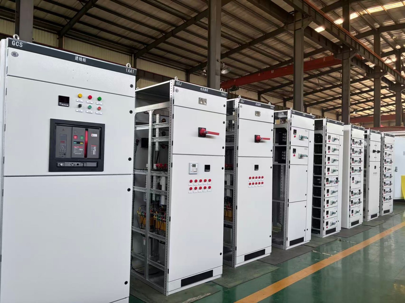
GCS low voltage switchgear is a low-voltage electrical distribution device designed for power conversion, distribution, and control in low-voltage power distribution systems. It is widely used as a power distribution and motor control center, as well as for capacitor compensation, in power plants, substations, industrial and mining enterprises, and high-rise buildings. Its structural design focuses on modularization, standardization, and withdrawable drawer units to achieve high reliability, operational safety, and convenient maintenance.
Do you know what components make up GCS low voltage switchgear? In this article, I will take you through the structure of this equipment and explain its main components in detail.
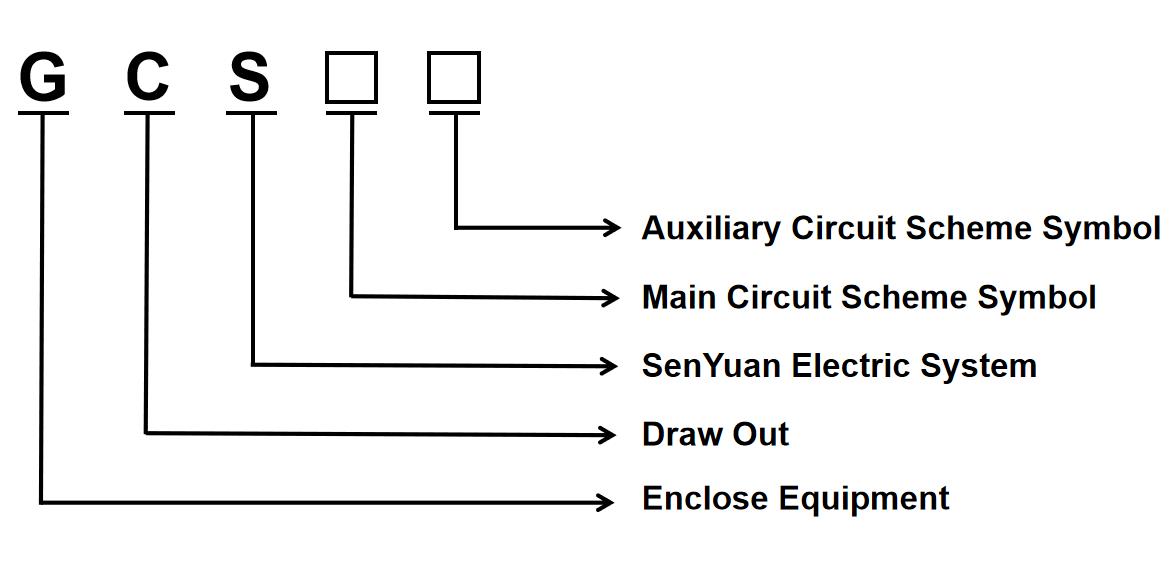
Product Model and Meaning
Structural Features of GCS Low Voltage Switchgear
Unlike MNS switchgear, which uses C-shaped profiles with a standard module of E=25 mm, the GCS low voltage switchgear frame features a modular assembly design. Its basic frame consists of KS-type profiles assembled with an E=20 mm modular system.
The GCS switchgear cabinet adopts a fully assembled modular structure. High-strength profiles, such as aluminum-zinc-coated steel sheets or high-quality cold-rolled steel sheets, are securely connected with high-strength self-tapping locking screws or Grade 8.8 hexagonal bolts to form the basic frame.
The internal cabinet dimensions, component dimensions, and compartment dimensions all follow the E=20 mm modular system.
A typical GCS low voltage switchgear cabinet is divided into three main compartments:
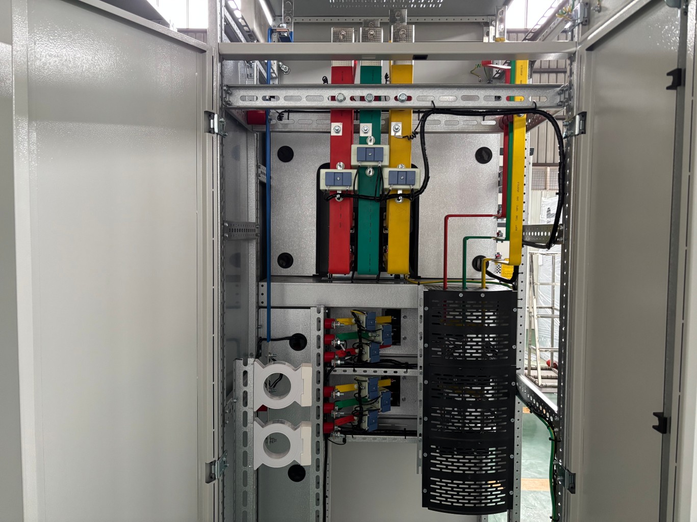
1. Busbar Compartment
Located at the top of the cabinet, the busbar compartment mainly houses the horizontal main busbars and vertical busbars. It usually features an independent metal cover that separates the busbar compartment from the functional units below, providing a high level of operational safety.
2. Functional Unit Compartment
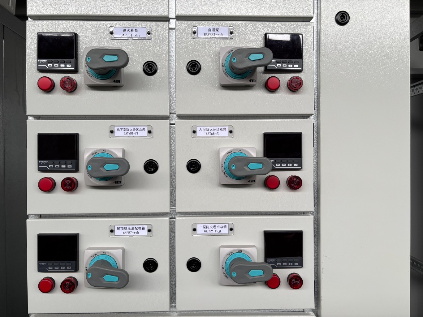
Also known as the drawer compartment, the functional unit compartment is the core area of the GCS switchgear cabinet. It accommodates various types and sizes of withdrawable functional units, commonly known as drawers.
This compartment also allows the cabinet height to be configured flexibly. Depending on the circuit current and component height, the drawers are available in several modular sizes, including 1/2 unit, 1 unit, 1.5 units, 2 units, and 3 units.
3. Cable Compartment
The cable compartment is located at the bottom of the cabinet. It provides sufficient space for connecting incoming and outgoing cables. A removable cover plate is usually provided to make cable installation, inspection, and maintenance easier.
In addition, a separate vertical busbar compartment is usually located at the rear of the cabinet. It separates the vertical busbars from the functional units and cable compartment. Galvanized steel plates or high-strength flame-retardant plastic functional plates separate the individual compartments, allowing each compartment to perform its specific function independently.
Metal plates with ventilation openings separate the upper and lower drawer functional units. This design helps prevent faults such as arc flash from electrical components from spreading to the busbars or other circuits.
The incoming and outgoing cable configurations typically include:
- Top entry and top exit
- Top entry and bottom exit
- Bottom entry and top exit
- Bottom entry and bottom exit
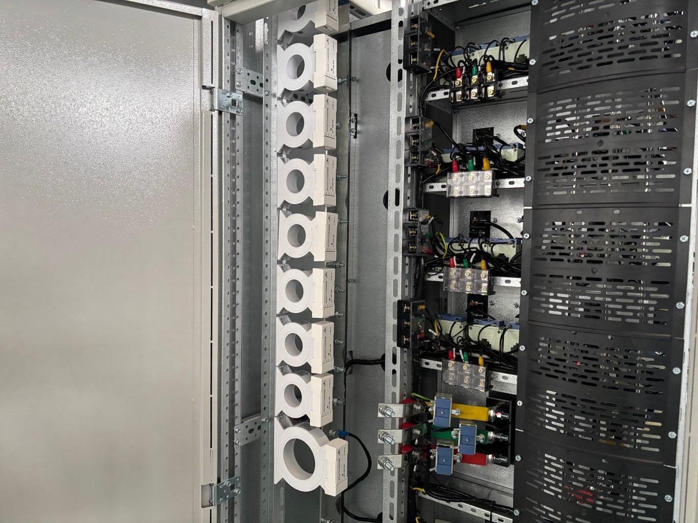
Common Cabinet Dimensions of GCS Low Voltage Switchgear
| Dimension | Size (mm) |
|---|---|
| Height | 2200 |
| Width | 400 / 600 / 800 / 1000 / 1200 |
| Depth | 800 / 1000 |
The drawer unit height is based on an 8E module, where 8E equals 160 mm. The drawer units typically come in five size series: 1/2 unit, 1 unit, 1.5 units, 2 units, and 3 units.
| Drawer Unit | 1/2 Unit | 1 Unit | 1.5 Units | 2 Units | 3 Units |
|---|---|---|---|---|---|
| Maximum continuous operating current (A) | 32 | 225 | 400 | 400 | 400 |
| Drawer dimensions (H*W*D, mm) | 160*280*410 | 160*560*410 | 240*560*410 | 320*560*410 | 480*560*410 |
The five drawer unit sizes can be assembled individually in the same cabinet or combined in a mixed configuration according to the requirements of the power distribution system.
The drawer units do not use a reliable mechanical interlocking device. Instead, the operating handle controls their operating positions. Clear markings indicate the connected, test, and withdrawn positions.
Analysis of Core Components
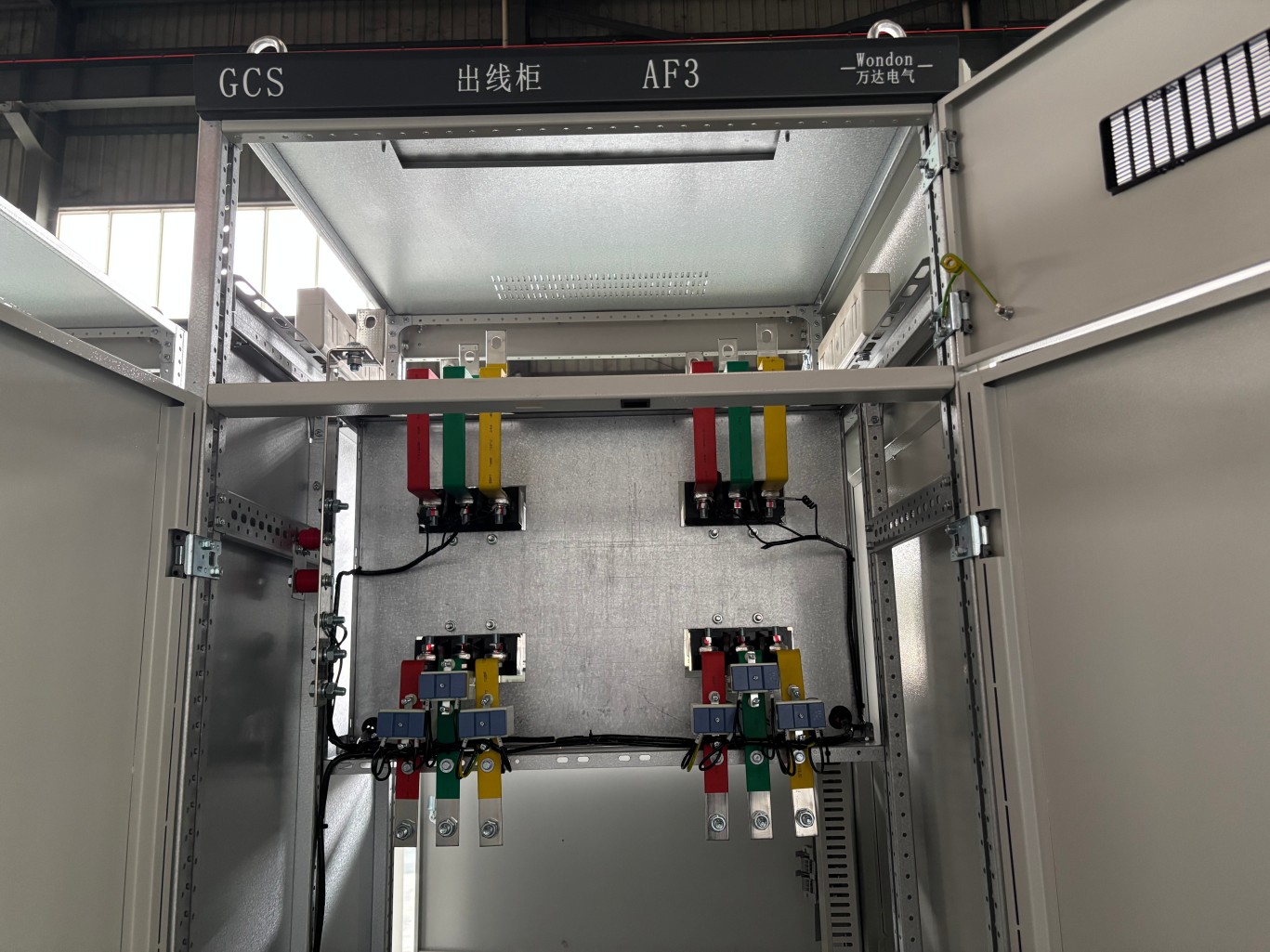
Busbar System
1. Horizontal Main Busbar
The horizontal main busbar is installed horizontally in the busbar compartment at the top of the cabinet. It generally uses copper busbars and can support a maximum rated current of up to 4000 A.
2. Vertical Busbar
The vertical busbar is installed in the busbar compartment at the rear of the cabinet and supplies power to each functional drawer.
It uses a specially designed profiled copper busbar with a “C” configuration that forms an “8”-shaped profile. This design provides reliable contact with the drawer plug-in connectors while ensuring sufficient short-circuit strength.
3. Neutral Busbar (N) and Protective Earth Busbar (PE)
The neutral busbar and protective earth busbar are usually arranged at the bottom of the cabinet in the cable compartment or at the rear of the cabinet.
Functional Units
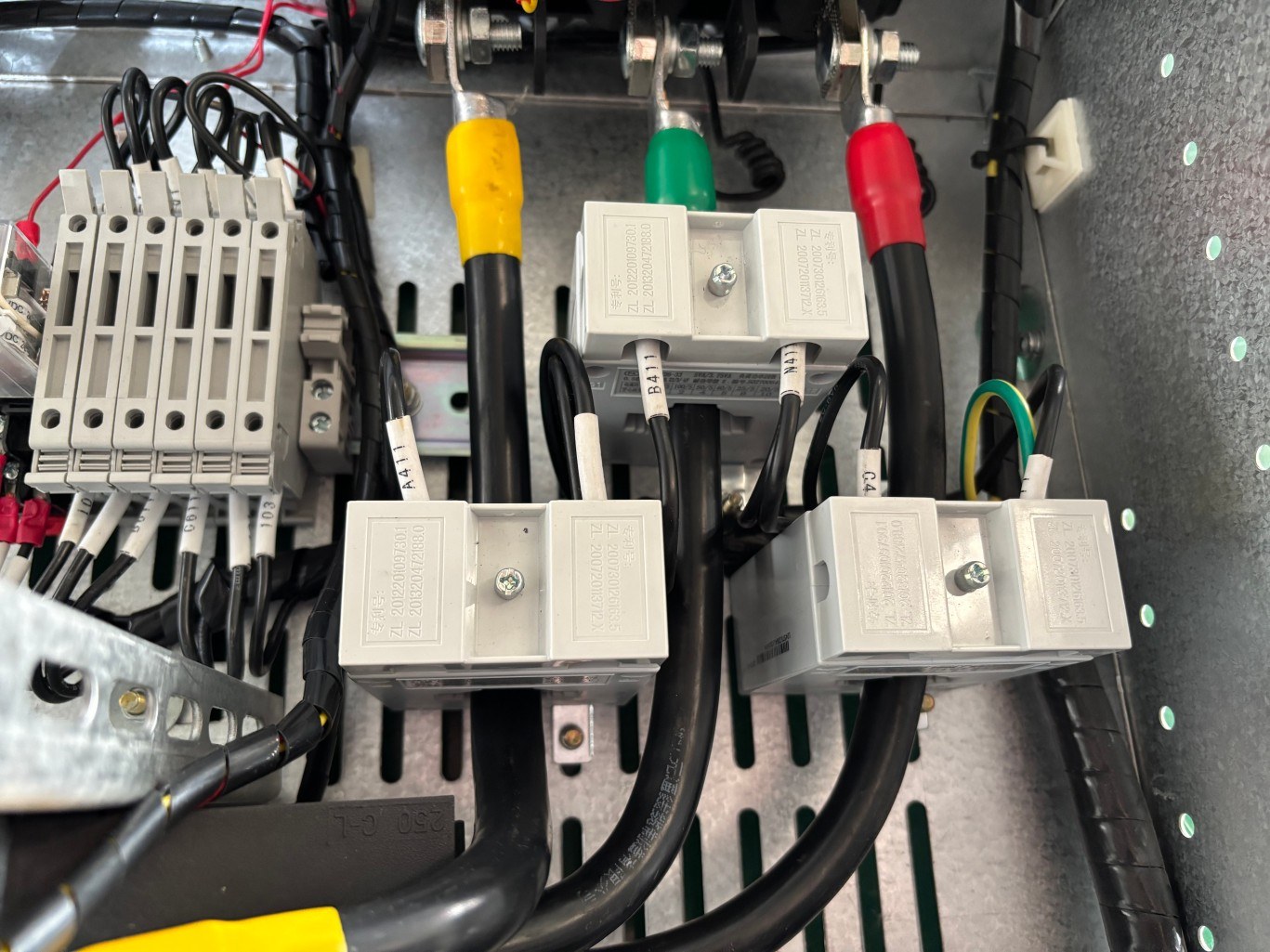
The functional unit is one of the most distinctive parts of GCS low voltage switchgear. Each drawer functions as an independent, withdrawable module.
1. Structure
Each drawer consists of steel plates and has three main operating positions.
① Connected Position
The drawer is fully inserted into the cabinet. Both the main circuit and secondary circuit are reliably connected, allowing the equipment to operate normally.
② Test Position
The drawer is pulled out by approximately one-third. The main circuit is disconnected, while the secondary circuit remains connected.
At this position, you can energize and test the control circuit and perform operating checks. This arrangement makes commissioning and testing safer and more convenient.
③ Isolated Position
The drawer is fully withdrawn or removed from the cabinet. Both the main and secondary circuits are completely disconnected, making inspection, maintenance, and replacement easier.
2. Electrical Interlocking
Each drawer incorporates a precision mechanical and electrical interlocking mechanism. The mechanism prevents the circuit breaker from closing when the drawer is not in the connected or test position. It also prevents the drawer from moving while the circuit breaker remains closed.
This interlocking design provides an important safeguard against incorrect operation and helps ensure safe operation of the GCS low voltage switchgear.
3. Standardization
The drawer dimensions follow standardized modular sizes, which makes factory preassembly and on-site configuration more convenient.
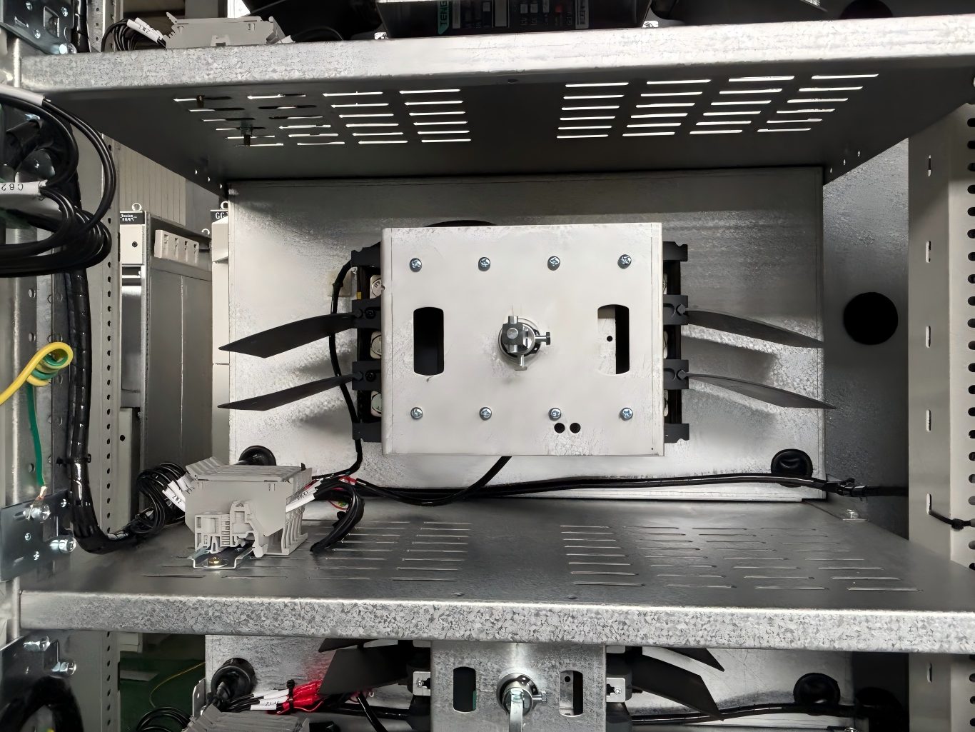
Primary Plug-in Connector System
Primary Fixed Contacts
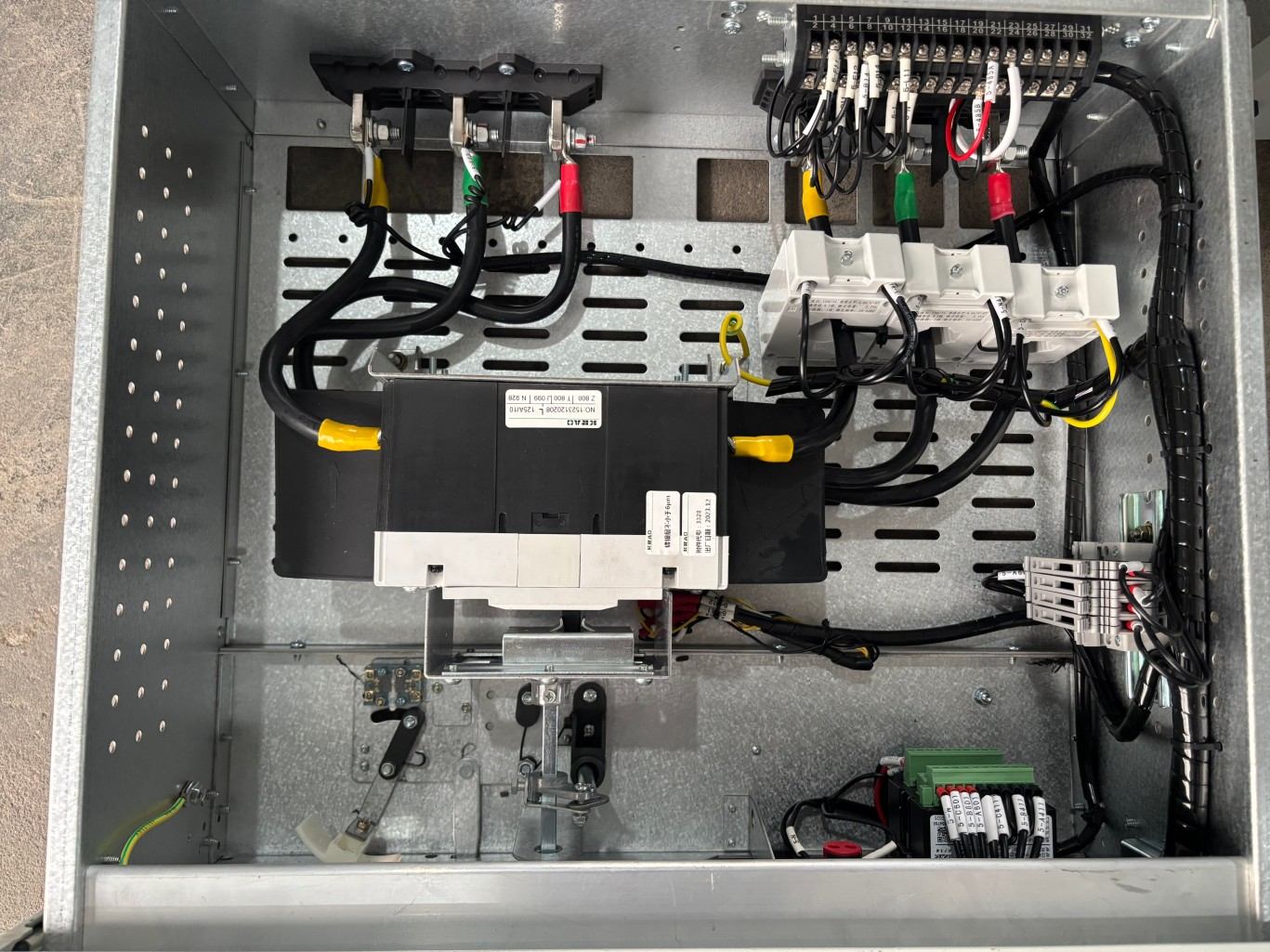
The primary fixed contacts are mounted on the vertical busbars of the cabinet frame or at the outgoing terminals.
Primary Moving Contacts
The primary moving contacts are installed at the rear of each drawer and connect with the fixed contacts.
They use high-quality alloy materials that provide good electrical conductivity, wear resistance, and resistance to welding. As a result, these contacts play a critical role in ensuring the reliable operation of withdrawable switchgear.
Secondary Plug-in Connector System
The secondary plugs and sockets use aviation-style secondary connectors.
Socket
The socket is fixed to the drawer body and connects the control components inside the drawer, such as relays, indicator lights, and meters.
Plug
A secondary connector is fixed to the cabinet frame and connects to the cabinet’s main secondary control wiring.
This design allows the secondary control circuit to remain connected when the drawer is in the test position, which is one of the key advantages of the GCS drawer system.
Protection and Safety Structure
Metal Partitions
Each compartment is separated by grounded metal plates. These partitions help prevent faults, such as arcs and short circuits, from spreading to adjacent compartments and equipment.
Pressure Relief Channel
A pressure relief cover is usually installed above the busbar compartment on the top of the cabinet.
If a severe internal arc fault occurs, the resulting high-temperature, high-pressure gas can discharge through the designated pressure relief path. This design helps protect personnel and adjacent equipment.
Doors and Panels
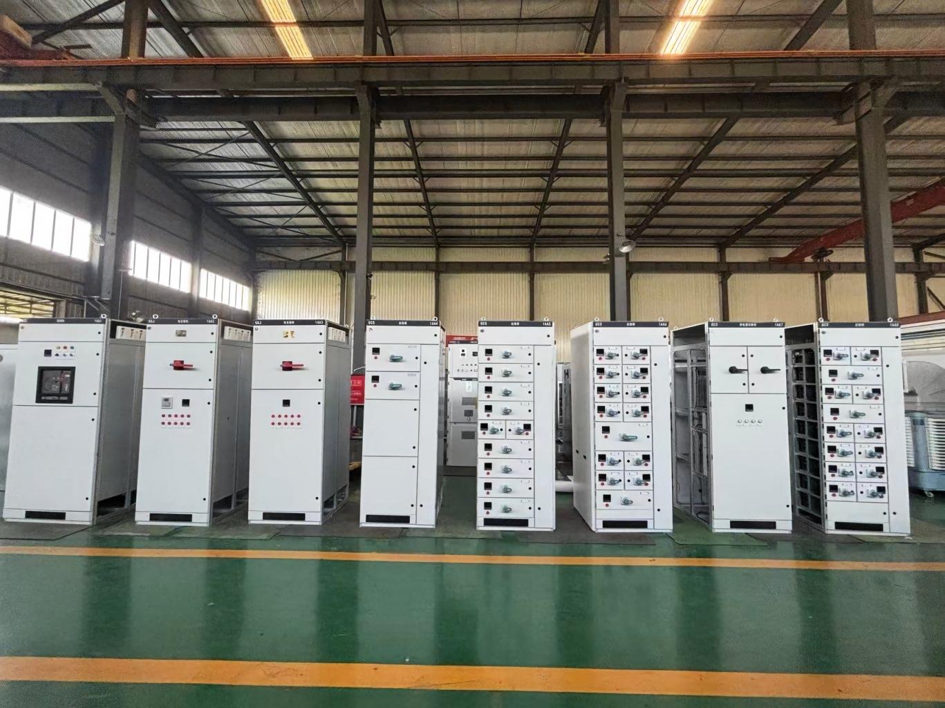
The front doors generally use tempered glass or metal panels, allowing operators to observe the internal operating status.
Drawer panels feature operating holes, circuit breaker open/close indicators, position indicators, and other operating and status indication components.
FAQs
1. What is GCS low voltage switchgear?
GCS low voltage switchgear is a modular low-voltage distribution and control system used for power distribution, motor control, and capacitor compensation in industrial and commercial applications.
2. What are the main compartments of GCS low voltage switchgear?
A GCS low voltage switchgear cabinet typically includes a busbar compartment, functional unit or drawer compartment, and cable compartment. A separate vertical busbar compartment is also commonly installed at the rear.
3. What are the operating positions of a GCS switchgear drawer?
A GCS switchgear drawer typically has three positions: connected, test, and isolated. These positions allow operators to perform normal operation, control circuit testing, maintenance, and replacement safely.
4. What is the function of the busbar system in GCS low voltage switchgear?
The busbar system distributes electrical power to the functional units. It typically includes horizontal main busbars, vertical busbars, a neutral busbar (N), and a protective earth busbar (PE).
5. What safety features does GCS low voltage switchgear have?
GCS low voltage switchgear uses compartmentalized construction, grounded metal partitions, mechanical and electrical interlocking, pressure relief channels, and clear drawer position indicators to improve operational safety and fault protection.
Conclusion
GCS low voltage switchgear combines a modular cabinet structure, withdrawable drawer units, reliable busbar systems, plug-in connectors, and multiple safety features to provide flexible and reliable power distribution and control. By understanding its structure and key components, you can select and configure the right GCS switchgear for your project requirements. If you are looking for GCS low voltage switchgear for an industrial, commercial, or power distribution project, contact our team to discuss your technical requirements and get a customized solution.