

When we plan a 10kV power distribution project, choosing the right switchgear is one of the most important decisions. The choice directly affects the reliability of the entire power distribution system, installation space, future maintenance, and long-term operating costs. Today, more and more power distribution projects are considering gas-insulated switchgear. Why is this becoming such a common choice?
Compared with traditional switchgear, gas-insulated switchgear typically offers a more compact structure, requires less installation space, and provides stronger adaptability to challenging environments. But what exactly is gas-insulated switchgear? What advantages does it offer? Where can you use it, and what technical requirements should you consider?
In this article, we will explore these questions and help you gain a clearer understanding of gas-insulated switchgear for 10kV power distribution projects.
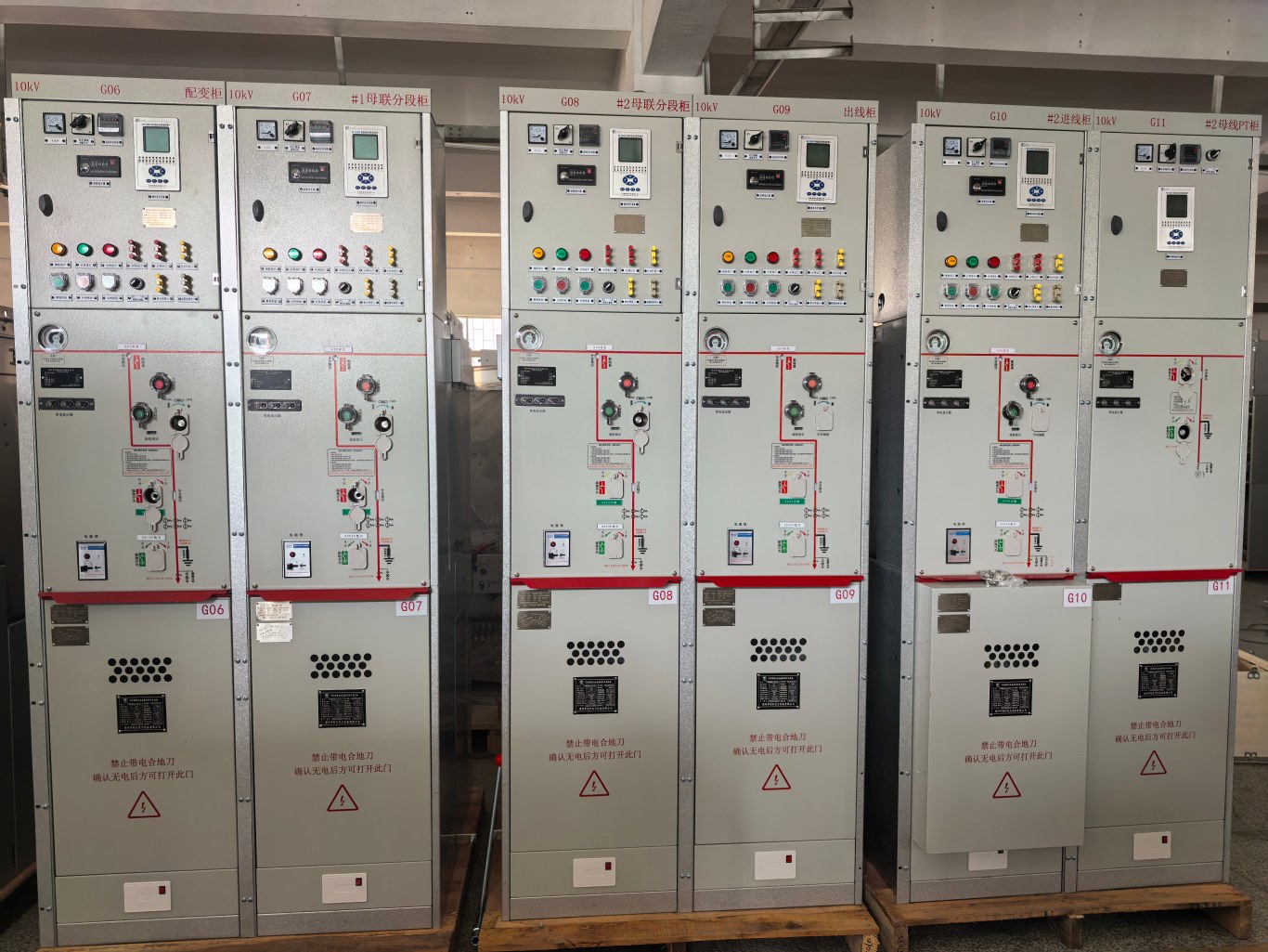
What Is Gas-Insulated Switchgear
Gas-insulated switchgear, often referred to as GIS, is a new generation of indoor AC metal-enclosed high-voltage switchgear.
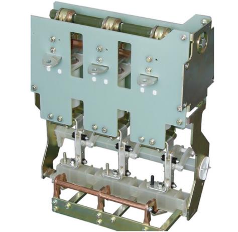
Its main switching device can use either a vacuum circuit breaker with a permanent magnetic operating mechanism or a vacuum circuit breaker with a spring operating mechanism.
The overall switchgear structure combines air insulation with gas-insulated compartments, typically using insulating gases such as sulfur hexafluoride (SF6). This design creates a compact yet expandable system that can support power distribution automation.
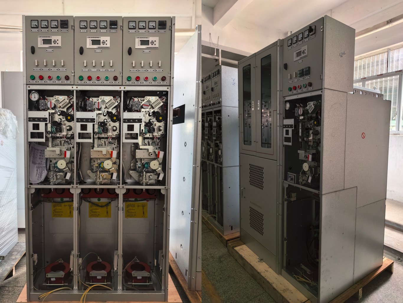
Key Features of Gas-Insulated Switchgear
1. Compact Structure, Flexible Operation, and Reliable Interlocking
Gas-insulated switchgear features a compact structure, flexible operation, and reliable interlocking functions.
For different application environments, especially harsh operating conditions, the equipment can support a variety of technical configurations to meet different user requirements.
2. Modular Design
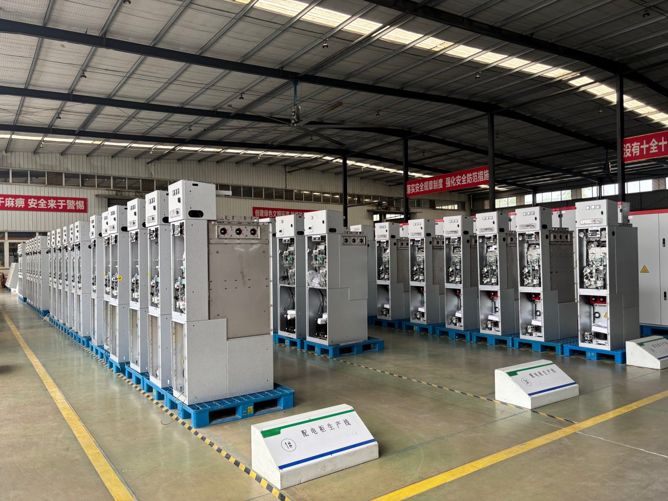
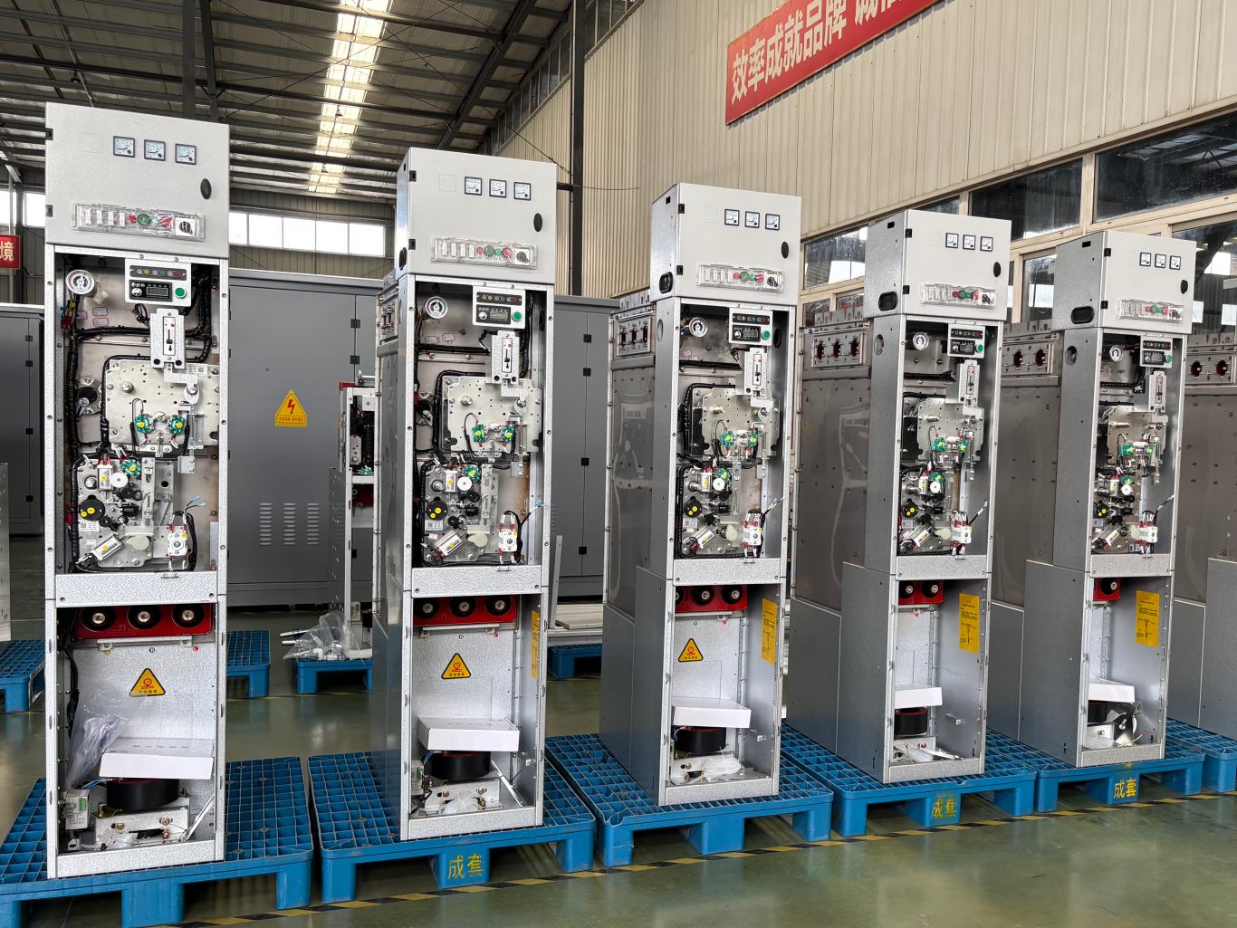
Gas-insulated switchgear uses a modular structural design. Manufacturers seal major high-voltage components inside compartments filled with insulating gas, such as SF6.
As a result, the switchgear cabinet can achieve a significantly smaller footprint. This design helps save valuable installation space and makes gas-insulated switchgear particularly suitable for projects with limited space or high land-use requirements.
3. High Sealing Performance
Gas-insulated switchgear offers excellent sealing performance and typically provides a high level of protection. Therefore, it can operate reliably in harsh environments and offers strong resistance to water and moisture.
In addition, the main electrical components operate inside sealed gas compartments. This design reduces the impact of dust, humidity, corrosion, and small animals on the equipment.
As a result, gas-insulated switchgear can achieve higher operational reliability while reducing maintenance requirements.
4. Flexible Configuration Options
Each gas compartment in gas-insulated switchgear can use an independent design. You can therefore combine different compartments to create a variety of circuit configurations.
This flexibility allows the switchgear to meet different power distribution and application requirements.
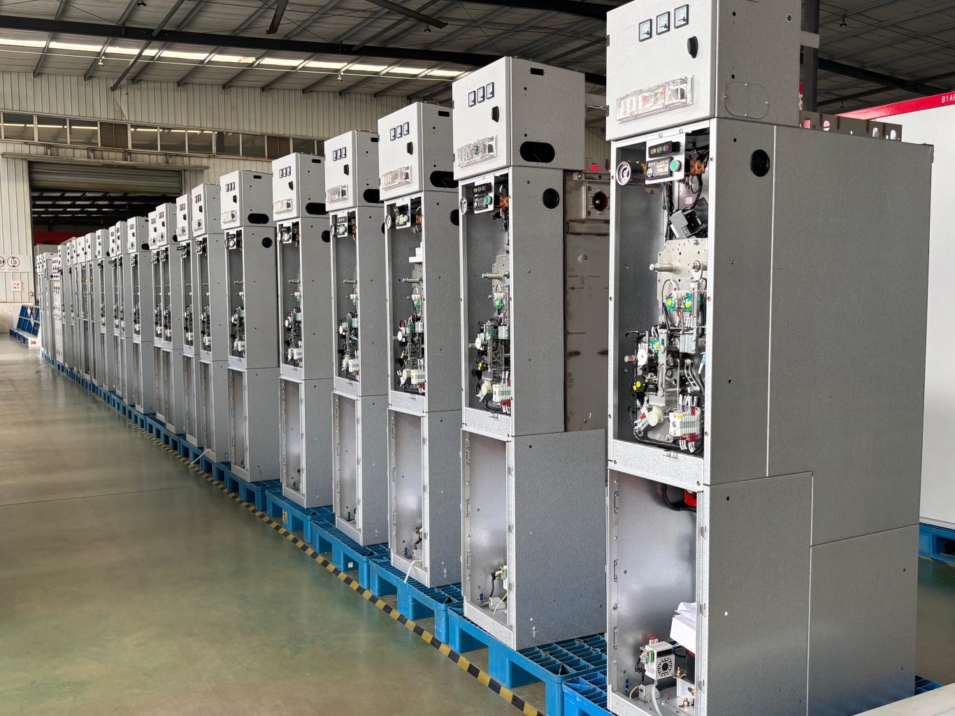
Applications and Uses of Gas-Insulated Switchgear
As technology continues to develop, gas-insulated switchgear is becoming increasingly intelligent. Modern systems can integrate control, protection, monitoring, and communication functions.
These functions allow operators to monitor equipment conditions in real time, identify potential problems, and take preventive measures when necessary.
Gas-insulated switchgear has a wide range of applications in power systems, including:
- Small secondary substations
- Switching stations
- Prefabricated substations
- Residential communities
- Industrial and mining enterprises
- Large commercial buildings and shopping centers
- Airports
- Metro systems
- Railway systems
- Other applications with high requirements for power supply reliability
In these environments, gas-insulated switchgear can help provide stable power distribution and reliable electrical safety.
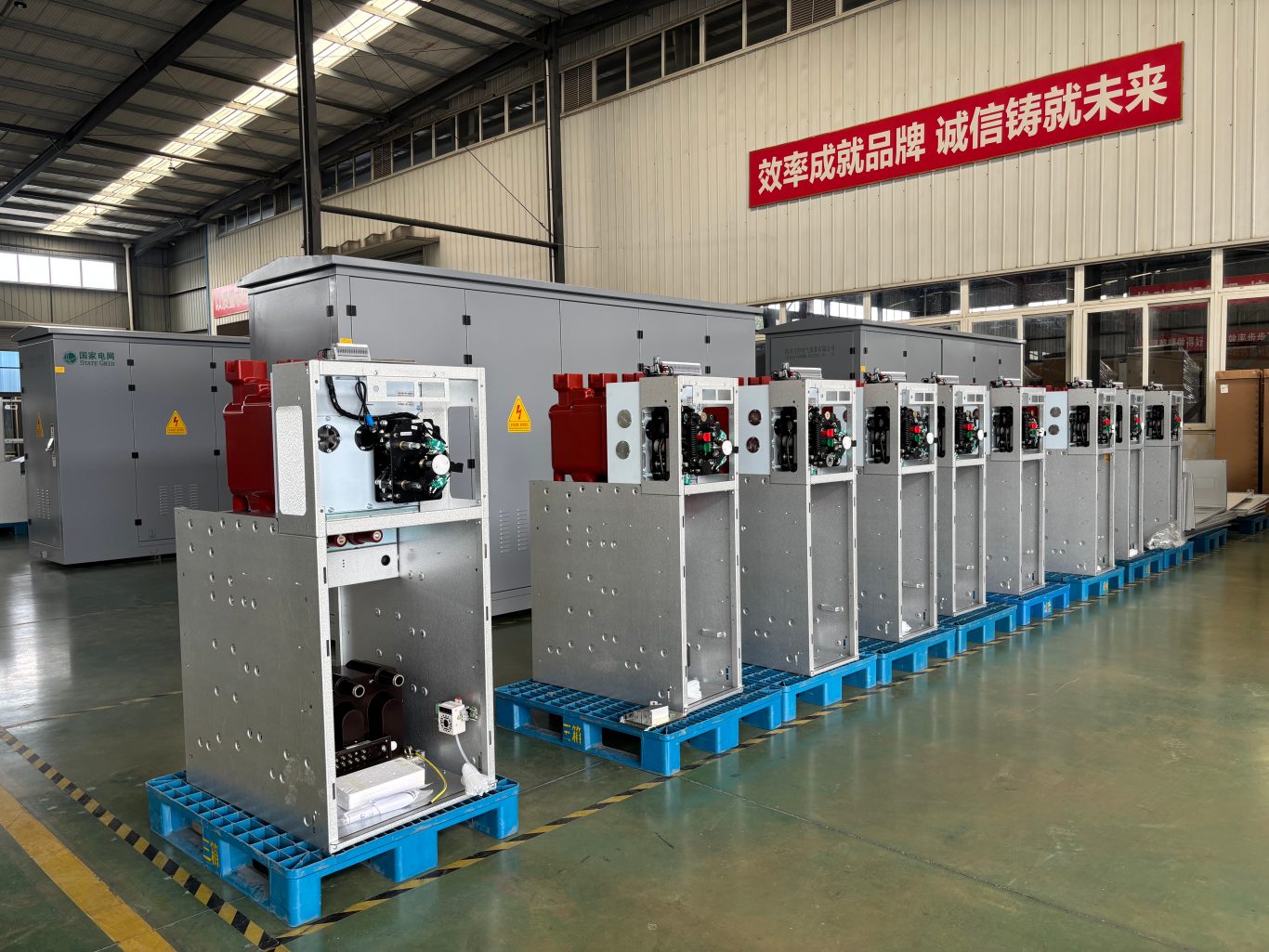
Technical Requirements for Gas-Insulated Switchgear Operating Mechanisms
Gas-insulated switchgear can use several different operating mechanisms, including F manual closing and electric opening mechanisms, V electric mechanisms, C electric mechanisms, and C manual mechanisms.
The following sections introduce the technical characteristics of these operating mechanisms.
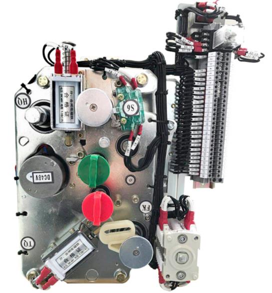
1. V Spring Operating Mechanism
The V spring operating mechanism mainly supports circuit breakers used in XGN15-12 high-voltage ring main units.
The mechanism uses a tension spring and an over-center mechanism to control the circuit breaker closing operation. For opening operations, it uses a compression spring energy-storage system.
This mechanism also supports automatic reclosing and includes interlocking functions with the isolating mechanism.
It offers high reliability, a mechanical service life of up to 10,000 operations, convenient installation, and strong environmental adaptability. It can also replace traditional circuit breaker operating mechanisms used in gas-insulated switchgear.
2. F Spring Operating Mechanism
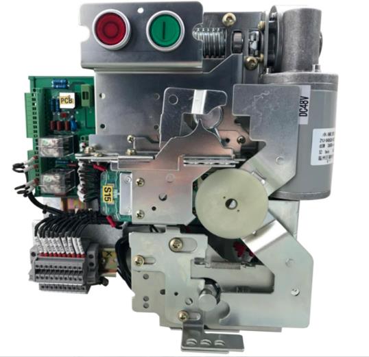
The F spring operating mechanism, also known as the XJ01-SC/DC spring mechanism, combines manual closing with electric opening operations.
Operators typically use manual closing during emergencies or as a backup when the electric operating system becomes unavailable. Electric opening, on the other hand, provides convenient, fast, and accurate operation.
The mechanism can store energy manually or electrically.
For manual energy storage, the operator uses a dedicated handle and rotates it clockwise by approximately 120 degrees. For electric energy storage, a motor drives the mechanism.
To close the switch, the operator can press the closing button or energize the closing coil electrically. The mechanism then releases the stored spring energy to complete the closing operation.
The opening operation works in a similar way. The operator can press the opening button or electrically energize the opening coil.
For grounding and closing operations, the operator inserts the handle into the lower part of the mechanism and rotates it clockwise by approximately 90 degrees. At this position, the main circuit cannot close.
To open the grounding circuit, the operator rotates the handle counterclockwise by approximately 90 degrees. After that, the mechanism can perform closing or grounding operations as required.
3. C Spring Operating Mechanism
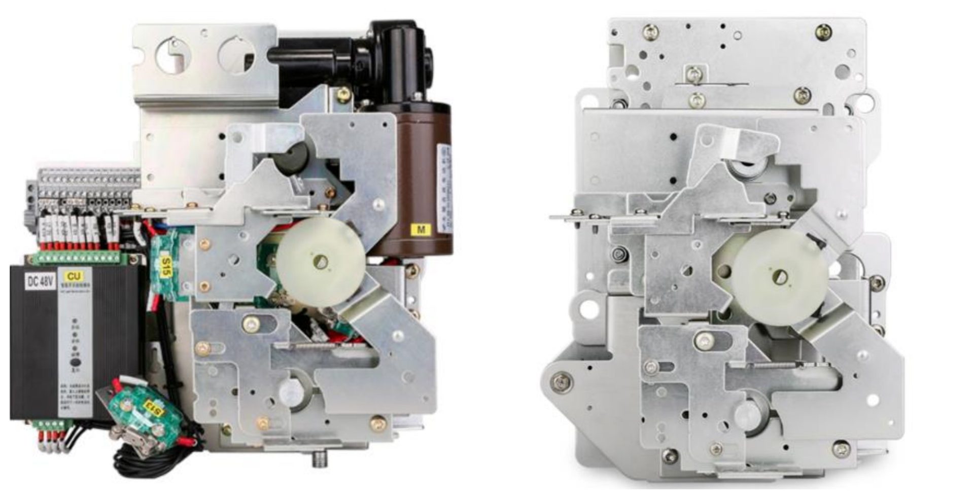
Similar to the V electric operating mechanism, the C electric operating mechanism also provides electric operation. However, its structure, performance, and application requirements may differ.
It also provides convenient, fast, and accurate operation.
The CF spring operating mechanism used with the XGN15-12 high-voltage ring main unit supports AC metal-enclosed switches with a rated voltage of 12kV.
This series of mechanisms uses a flat spiral spring energy-storage system to control load switch operations. For grounding operations, it uses a compression spring over-center energy-storage mechanism.
The mechanism includes three operating positions:
- Closing position
- Opening position
- Grounding position
This series also provides five interlocking protection functions, a compact structure, convenient installation, and strong environmental adaptability.
The closing operation supports both manual and electric methods.
For manual closing, the operator rotates the handle clockwise by approximately 90 degrees and uses the stored spring force to close the main circuit.
For electric closing, the operator presses the closing button, and the motor drives the mechanism.
The opening operation also supports manual and electric methods. For manual opening, the operator rotates the handle counterclockwise by approximately 90 degrees. For electric opening, the operator presses the opening button.
Grounding closing and opening operations take place at the lower part of the mechanism.
Rotating the handle clockwise by approximately 90 degrees closes the grounding circuit, while rotating it counterclockwise by approximately 90 degrees opens the grounding circuit.
During grounding operations, the main circuit cannot perform a closing operation.
Technical Requirements for Gas-Insulated Switchgear Switching Devices
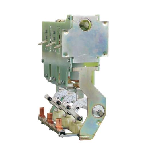
Requirement 1: Two-Position Circuit Breaker With Isolation and Without Grounding
A gas-insulated switchgear circuit breaker is a high-voltage circuit breaker installed inside a gas-insulated switchgear system.
It uses insulating gas, such as SF6, to improve insulation performance and arc-extinguishing capability.
A two-position design means that the circuit breaker has two operating positions:
- Closing position
- Opening position
The isolation function allows the circuit breaker to provide electrical isolation. When the breaker opens, the system can create a clear isolation point to ensure safe circuit separation.
A design without grounding means that the circuit breaker does not include a grounding function.
Requirement 2: Technical Requirements for Earthing Switches
A gas-insulated switchgear earthing switch should provide stable current transmission and sufficient mechanical strength.
It must withstand the electrodynamic forces and thermal stress generated by short-circuit currents.
The earthing switch should also provide reliable insulation performance to reduce the risk of electrical accidents.
In addition, the operating mechanism should complete grounding operations accurately and quickly.
Good sealing performance helps prevent moisture, dust, and other contaminants from entering the equipment.
The switch should also provide strong weather resistance to adapt to harsh environmental conditions and good corrosion resistance to extend its service life.
Requirement 3: Technical Requirements for Disconnect Switches
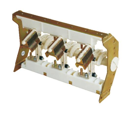
First, the disconnect switch should provide reliable insulation performance.
Manufacturers can use high-quality insulating materials, such as epoxy resin and silicone rubber, to help prevent insulation breakdown during long-term operation.
Second, the mechanical structure must provide sufficient strength and rigidity to withstand electromagnetic forces and thermal stress.
The operating mechanism should remain flexible and reliable to achieve fast and accurate opening and closing operations.
Sealing performance also plays an important role.
The design can use high-temperature-resistant and aging-resistant materials, such as fluororubber and silicone rubber. Advanced sealing technologies can also help prevent gas leakage.
Conductive components should use high-purity metals with low electrical resistance, such as copper and aluminum.
Special treatment of contact surfaces can further improve operational stability and reliability.
The protection level should meet requirements such as IP65 or IP67.
The enclosure can use corrosion-resistant and impact-resistant materials, including stainless steel and aluminum alloy, together with appropriate waterproof, dustproof, and corrosion-resistant measures.
In addition, the gas-insulated switchgear disconnect switch should provide strong environmental adaptability and operate reliably under high temperatures, low temperatures, humidity, salt spray, and other harsh environmental conditions.
Requirement 4: Two-Position Load Switch
A two-position gas-insulated switchgear load switch has only two operating positions:
- Closing position, also known as the connected position
- Opening position, also known as the disconnected position
Technical requirements include reliable operation under specified rated voltage and current conditions.
The switch should provide good insulation performance to prevent electrical breakdown or flashover.
It should also withstand short-circuit currents and disconnect the circuit promptly during faults to protect the equipment and the power distribution system.
In addition, the operating mechanism should remain flexible and reliable and require an appropriate operating force.
The switch should provide a clear position indication system so that operators can accurately determine its operating status.
Its mechanical service life should also meet operational requirements and maintain stable performance throughout the specified number of operating cycles.
Requirement 5: Three-Position Load Switch
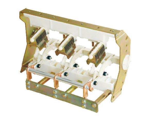
A three-position gas-insulated switchgear load switch includes three clearly defined operating positions:
- Operating (closing) position: The contacts close and allow current to flow.
- Isolation (opening) position: The contacts separate and disconnect the circuit, ensuring complete isolation from the power supply during maintenance or inspection.
- Grounding (maintenance) position: This position allows grounding operations or circuit condition testing after the equipment has been isolated.
The technical requirements are generally the same as those for the two-position load switch.
Requirement 6: Three-Position Vacuum Circuit Breaker
A three-position gas-insulated switchgear vacuum circuit breaker is a high-voltage switching device that includes three operating positions:
- Closing position: Used to connect the circuit during normal power system operation.
- Isolation position: Used to disconnect the circuit and isolate the equipment during power outages, maintenance, or fault handling.
- Grounding position: Used to connect the equipment to the grounding system during maintenance or inspection to help prevent electric shock, short circuits, and other hazardous conditions.
The technical requirements include the following:
The circuit breaker should operate normally under specified rated voltage and current conditions and provide sufficient short-circuit withstand capability and insulation performance.
The operating mechanism should remain flexible and reliable and allow switching between the closing, opening, and grounding positions.
It should also include a clear position indication system and mechanical interlocking devices to help prevent incorrect operations.
In addition, its mechanical service life should meet operational requirements.
The circuit breaker should operate reliably within specified temperature, humidity, and altitude ranges. It should also resist adverse conditions such as chemical corrosion, vibration, and pollution.
Finally, the equipment should include a reliable grounding protection system, and the operating mechanism should consider operator safety.
FAQs
1. What is gas-insulated switchgear used for?
Gas-insulated switchgear is used for medium-voltage power distribution, especially in applications where installation space is limited or environmental conditions are challenging. Common applications include secondary substations, ring main units, prefabricated substations, industrial facilities, commercial buildings, airports, metro systems, and railway projects.
2. Why is gas-insulated switchgear suitable for 10kV power distribution projects?
Gas-insulated switchgear is suitable for 10kV power distribution projects because it combines a compact structure, reliable insulation performance, flexible configuration, and strong environmental adaptability. It can also help reduce installation space and maintenance requirements.
3. What is the difference between gas-insulated switchgear and air-insulated switchgear?
The main difference is the insulation method. Gas-insulated switchgear uses insulating gas in sealed compartments to protect key electrical components, while air-insulated switchgear mainly relies on air insulation. Gas-insulated switchgear usually requires less installation space and provides better protection against dust, moisture, and other environmental factors.
4. How do I choose the right gas-insulated switchgear for my project?
When choosing gas-insulated switchgear, you should consider the rated voltage, rated current, short-circuit withstand capability, installation environment, available space, circuit configuration, protection requirements, and future expansion needs. For complex projects, working with an experienced switchgear manufacturer can help you select a suitable technical solution.
5. Does gas-insulated switchgear require frequent maintenance?
Gas-insulated switchgear generally requires less maintenance than conventional open electrical equipment because its main components operate inside sealed compartments. The sealed design helps protect the equipment from dust, humidity, corrosion, and other environmental factors. However, regular inspection and maintenance should still follow the manufacturer’s technical requirements.
Conclusion
Choosing the right switchgear can directly affect the reliability, installation efficiency, maintenance requirements, and long-term operating costs of a 10kV power distribution project.
With its compact structure, modular design, high sealing performance, flexible configuration options, and strong environmental adaptability, gas-insulated switchgear provides an effective solution for many modern medium-voltage power distribution applications. It is particularly suitable for projects with limited installation space or demanding operating environments.
However, selecting the right gas-insulated switchgear requires more than simply choosing a standard model. Rated voltage, current capacity, short-circuit performance, circuit configuration, operating mechanisms, protection requirements, and installation conditions should all match the requirements of your project.
If you are planning a 10kV power distribution project and looking for a suitable gas-insulated switchgear solution, our team can help you evaluate your technical requirements and provide customized switchgear solutions based on your application. Contact us to discuss your project specifications and request technical support or a quotation.