

When engineers compare switchgear vs RMU, the first point to understand is that they are not two completely separate types of equipment.
An RMU, or Ring Main Unit, is a type of medium voltage switchgear designed mainly for compact secondary distribution. You will often find it at transformer substations, load connection points, and ring distribution networks.
In simple terms, all RMUs are medium voltage switchgear, but not all medium voltage switchgear is an RMU.
The main difference comes from their design purpose. RMUs focus on compact construction, ring network operation, and standardized secondary distribution. Conventional MV switchgear, by comparison, offers more flexibility for feeders, protection, metering, busbar arrangements, and future expansion.
As a result, the right choice depends on several factors, including network topology, load current, short-circuit level, protection requirements, installation space, automation needs, and future expansion.
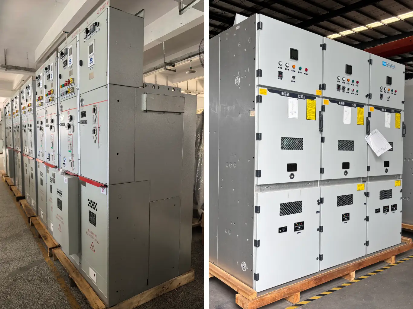
What Is the Difference Between MV Switchgear and RMU?
What Is Medium Voltage Switchgear?
Medium voltage switchgear is a broad category of electrical equipment that controls, protects, and isolates medium voltage circuits. Depending on the system design, it can also provide metering and monitoring functions.
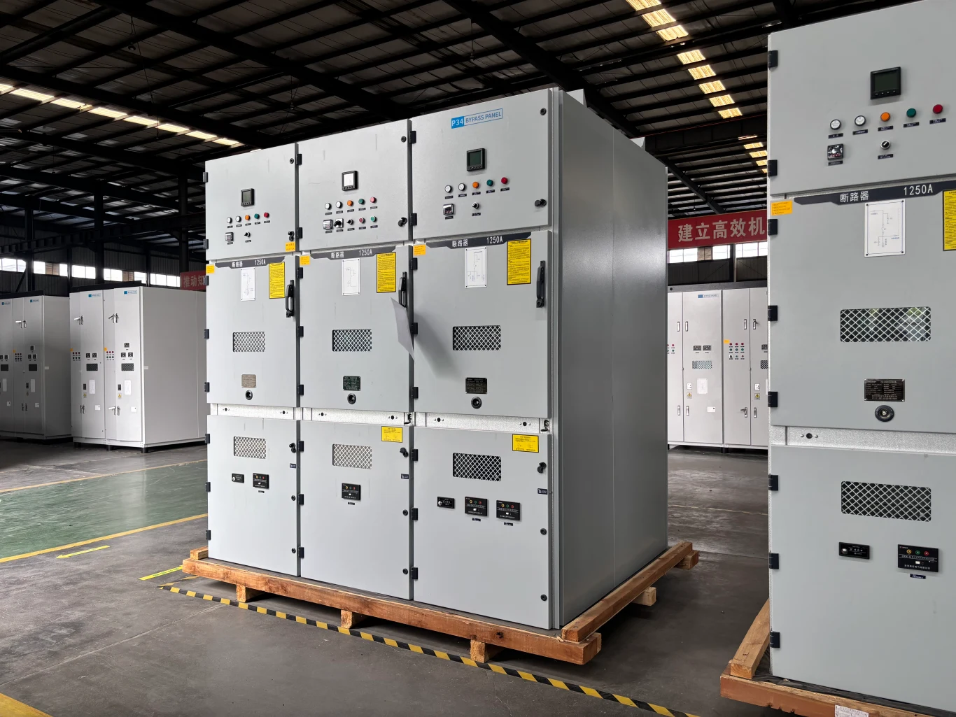
For example, a typical MV switchgear lineup may include incoming panels, outgoing feeder panels, circuit breaker panels, metering panels, bus couplers, voltage transformer panels, and protection or control equipment.
Because engineers can configure the lineup in different ways, MV switchgear can serve radial networks, ring networks, industrial plants, substations, renewable energy projects, and many other applications.
The exact voltage range varies with the product design, applicable standards, and target market. Therefore, always check the rated voltage of the selected equipment instead of assuming that every MV switchgear product covers the same voltage range.
What Is an RMU?
An RMU, or Ring Main Unit, is a compact medium voltage switchgear assembly mainly designed for secondary distribution.
Depending on the configuration, it may combine load-break switches, earthing switches, fuse-switch combinations, vacuum circuit breakers, protection devices, and monitoring or automation functions in one enclosure.
This compact structure makes RMUs particularly useful at transformer substations and load connection points where installation space is limited.
At the same time, RMU technology is not limited to one insulation method. Depending on the design, an RMU can use SF₆, dry air, other SF₆-free technologies, or solid insulation. Therefore, RMU should not be treated as a synonym for SF₆ switchgear.
Is RMU a Type of Medium Voltage Switchgear?
Yes. An RMU is a specialized form of medium voltage switchgear.
The term “switchgear” describes the broader equipment category, while “RMU” describes a specific compact configuration and its typical application.
For instance, a modular MV switchgear lineup may contain several independent functional panels. An RMU, on the other hand, normally combines several switching functions into a compact assembly.
Therefore, when comparing RMU vs MV switchgear, the key question is whether the selected configuration can meet the project’s electrical, protection, and operational requirements.
RMU vs MV Switchgear: Key Differences
The differences between these two solutions mainly come from their design objectives and typical applications.
| Feature | RMU | Conventional MV Switchgear |
|---|---|---|
| Typical application | Secondary distribution | Primary and secondary distribution |
| Main design focus | Compactness and ring networks | Flexibility and complex distribution |
| Configuration | Compact and standardized | Modular and highly configurable |
| Typical protection | Fuse or circuit breaker | VCB and protection relays |
| Expansion | Limited to moderate, depending on design | Generally more flexible |
| Installation space | Compact | Usually larger |
| Automation | Available on smart models | Highly configurable |
Network Topology
RMUs are commonly associated with ring or loop distribution networks.
For example, a typical arrangement may include two ring feeders and one transformer feeder. If a cable section develops a fault, operators can isolate the affected section while healthy sections may continue receiving power from an available source.
However, an RMU does not create redundancy by itself. The network still needs a suitable alternative power source and an appropriate switching strategy.
Conventional MV switchgear can also support ring networks. In addition, engineers can configure it for radial feeders, multiple incoming sources, bus sections, and other system arrangements.
For this reason, network topology is one of the most important factors when comparing switchgear vs RMU.
Equipment Configuration and Footprint
Compact construction is one of the main advantages of an RMU. By combining several switching functions into one enclosure, it can reduce the space required for a substation.
This makes RMUs useful in urban substations, kiosk substations, commercial buildings, and other locations where floor space is limited.
In contrast, conventional MV switchgear usually uses separate functional panels for incoming supplies, outgoing feeders, metering, bus coupling, or transformer protection. This arrangement may require more space, but it also gives engineers greater freedom to configure the system.
Switching and Protection
The switching technology depends on the specific RMU configuration.
A basic RMU may use load-break switches for ring feeders and a fuse-switch combination for transformer protection. More advanced designs can use vacuum circuit breakers together with protection relays.
Conventional MV switchgear commonly uses vacuum circuit breakers with dedicated protection relays. This configuration can support more detailed protection settings and coordination.
Therefore, RMU does not automatically mean fuse protection. Circuit breaker-based RMUs are also available when a project requires more advanced protection and control.
Expansion and Flexibility
A standard RMU often follows a predefined configuration. This approach works well when a project has a limited number of feeders and a relatively stable distribution structure.
Some RMU designs, however, allow additional functional units or extensions. This gives engineers more flexibility when the network may grow in the future.
Conventional MV switchgear generally provides more freedom when a project requires several feeders, busbar sections, metering functions, or future modifications.
For projects with uncertain load growth, it is therefore worth considering expansion requirements during the initial design stage.
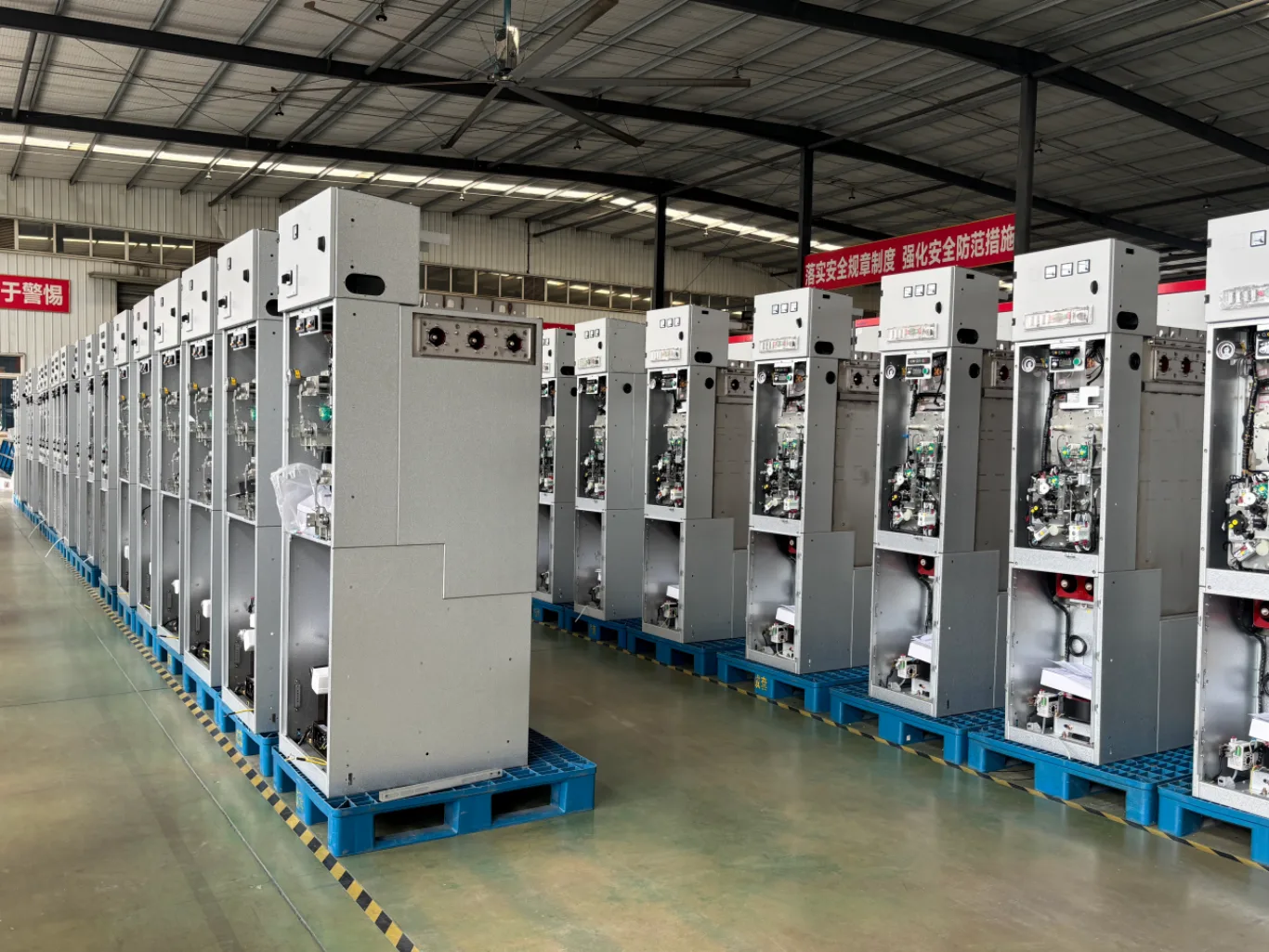
How Do RMU and MV Switchgear Differ in Design?
Size and Footprint
Compact size is one of the main reasons engineers choose to consider an RMU.
Its switching components and cable connections fit within a compact enclosure, which can simplify installation in substations with limited floor space.
Conventional MV switchgear normally uses separate panels for different functions. As the number of feeders and protection functions increases, the overall lineup can become larger.
However, physical size should not become the only selection criterion. The equipment still needs to meet the required electrical ratings, safety requirements, protection functions, and maintenance strategy.
Switching Devices
The switching devices depend on the application and the RMU configuration.
For a basic transformer feeder, a load-break switch and fuse-switch combination may provide the required functions. When the project needs more flexible protection, engineers can specify a vacuum circuit breaker with a protection relay.
Meanwhile, conventional MV switchgear commonly uses vacuum circuit breakers because they work well with configurable protection relays and controlled fault interruption.
The choice between fuses and circuit breakers should therefore follow the actual load, fault level, and protection requirements.
Protection and Control
Protection requirements can create a significant difference between an RMU and conventional MV switchgear.
A simple transformer feeder may only need fuse protection, while an industrial feeder could require configurable overcurrent and earth-fault protection. Depending on the application, engineers may also need directional, voltage, frequency, transformer, or grid-connection protection.
When a project requires advanced relay settings and detailed protection coordination, a VCB-based configuration can provide greater flexibility.
Maintenance
Sealed RMU designs can reduce the exposure of internal components to dust, humidity, and other environmental conditions.
However, sealed does not mean maintenance-free.
Operators still need to inspect areas such as cable terminations, earthing connections, operating mechanisms, interlocks, protection systems, auxiliary power, and communication equipment.
Conventional MV switchgear may provide easier access to individual functional panels for inspection, testing, replacement, or future modification. The actual maintenance requirements depend on the equipment design and manufacturer’s instructions.
How Can an RMU Support Distribution Reliability?
An RMU can contribute to distribution reliability when engineers integrate it into a suitable network design.
The equipment itself does not guarantee higher reliability. Instead, network topology, protection coordination, switching strategy, automation, and alternative power sources all influence the final result.
Fault Isolation and Load Transfer
In a ring network, an RMU can help isolate a faulted cable section.
Once the faulty section is disconnected, healthy parts of the network may continue receiving power through an alternative supply path. This can reduce the number of loads affected by a single cable fault.
The actual restoration process depends on the available source capacity, switching sequence, protection coordination, and operating rules.
Remote Operation and Distribution Automation
Modern RMUs can integrate motorized switches, fault indicators, sensors, communication interfaces, and remote-control functions.
With these functions, operators can monitor network conditions and control switching devices without visiting every installation point.
For larger distribution networks, RMUs can also form part of a distribution automation or FDIR system.
FDIR stands for Fault Detection, Isolation, and Restoration. A complete FDIR solution may combine RMUs with sensors, motorized switches, RTUs or FTUs, communication networks, control software, and protection logic.
Therefore, an RMU alone does not guarantee automatic power restoration. The network must also provide an alternative supply and the necessary automation functions.
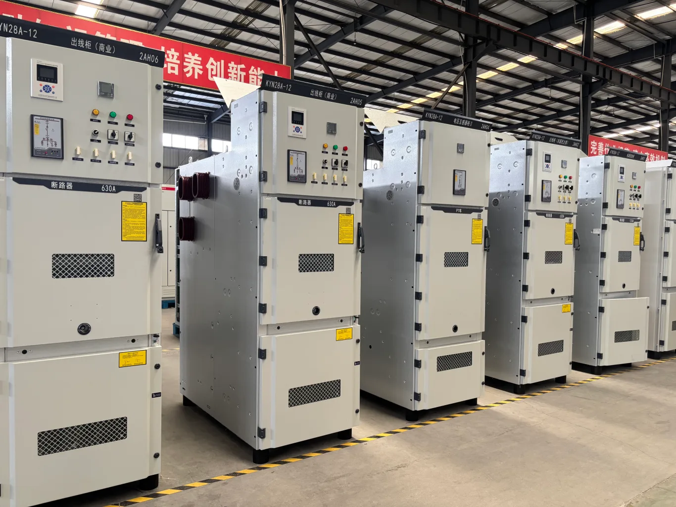
RMU vs MV Switchgear: Which One Fits Your Project?
There is no universal choice between RMU and conventional MV switchgear. The appropriate solution depends on the electrical system, project requirements, and future operating conditions.
| Project condition | Equipment to consider | Main reason |
|---|---|---|
| Compact secondary substation | RMU | Small footprint and compact configuration |
| Urban cable distribution | RMU | Suitable for ring distribution |
| Ring network with limited feeders | RMU | Designed for compact ring applications |
| Standard transformer feeder | RMU or fuse-switch RMU | Simple and compact protection |
| Multiple MV outgoing feeders | Modular MV switchgear | Greater configuration flexibility |
| Complex protection coordination | VCB-based MV switchgear or CB-based RMU | More flexible relay protection |
| Future feeder expansion | Modular or extensible MV switchgear | Easier system expansion |
| Solar PV collection system | RMU or MV switchgear | Depends on protection and grid requirements |
| BESS grid connection | CB-based RMU or MV switchgear | Requires detailed protection and control |
RMU for Urban and Commercial Projects
Urban distribution networks often have limited installation space, so compact equipment can simplify substation design.
For this reason, an RMU can work well in compact substations and cable-fed load points. Commercial buildings may also use RMUs when they have a limited number of feeders and relatively straightforward protection requirements.
Larger facilities may have multiple incoming sources, several feeders, or more complex protection schemes. In those cases, modular MV switchgear can provide more configuration options.
MV Switchgear for Industrial Projects
Industrial facilities often have more complex electrical systems than standard commercial buildings.
Multiple transformers, motors, process loads, large feeders, and critical production equipment can all increase protection and switching requirements.
As a result, engineers need to consider short-circuit level, protection coordination, feeder quantity, switching requirements, metering, and future expansion.
Where the system requires multiple feeders and complex protection functions, modular MV switchgear can provide greater configuration flexibility.
RMU or MV Switchgear for Solar PV and BESS
Solar PV and BESS projects require more than a simple comparison of equipment size.
The electrical system may need to handle inverter behavior, transformer protection, reverse power flow, grid protection, communication, remote control, and utility requirements.
An RMU can suit some transformer or collection points. However, larger systems with more complex protection and control requirements may call for a circuit breaker-based RMU or modular MV switchgear.
For BESS projects, engineers should also consider bidirectional power flow and different operating modes when developing the protection scheme.
What Should You Check Before Selecting RMU or MV Switchgear?
Before choosing between RMU and conventional MV switchgear, review the complete electrical system rather than focusing on the equipment type alone.
System Voltage and Rated Current
Start with the system voltage and expected load.
Common distribution levels include 6 kV, 10 kV, 11 kV, 20 kV, 22 kV, 24 kV, and 33 kV. However, the selected equipment must match the actual system voltage and required insulation level.
Rated current also needs to match the expected load. Transformer capacity, feeder demand, future load growth, ambient temperature, and applicable derating factors can all affect the required current rating.
Short-Circuit Level
The prospective short-circuit current is another critical selection parameter.
The selected equipment must provide suitable short-time withstand current, peak withstand current, and short-circuit breaking capacity for the installation point. Fault clearing time should also match the protection design.
Therefore, engineers should determine the required fault rating through the electrical system study rather than selecting a value based only on whether the equipment is an RMU or conventional MV switchgear.
Protection and Control Requirements
The protection scheme should match the feeder and overall system requirements.
For example, a simple transformer feeder may use a fuse-switch combination, while a more complex feeder may require a VCB and protection relay. Depending on the application, the system may also need overcurrent, earth-fault, directional, voltage, frequency, transformer, or grid-connection protection.
Automation should also be considered at this stage. If the project requires motorized operation, remote control, fault indication, RTU or FTU integration, or SCADA communication, these functions should form part of the initial equipment specification.
Feeder Quantity and Future Expansion
The number of feeders required today does not always represent the final system configuration.
If the project may add transformers, outgoing feeders, or bus sections later, the switchgear should provide enough expansion capability. Modular MV switchgear often offers greater flexibility for projects with uncertain future requirements, while some RMU designs can also support additional functional units.
Installation Environment
The installation environment can directly affect the equipment specification.
For example, high temperatures may affect equipment derating, while humidity and condensation can increase insulation concerns. Coastal locations may also require additional consideration for salt contamination.
In addition, the project should define whether the equipment will operate indoors or outdoors and specify the required enclosure protection, internal arc performance, altitude considerations, and applicable local standards.
Reviewing these conditions early helps engineers select an RMU or MV switchgear configuration that matches the actual installation environment.
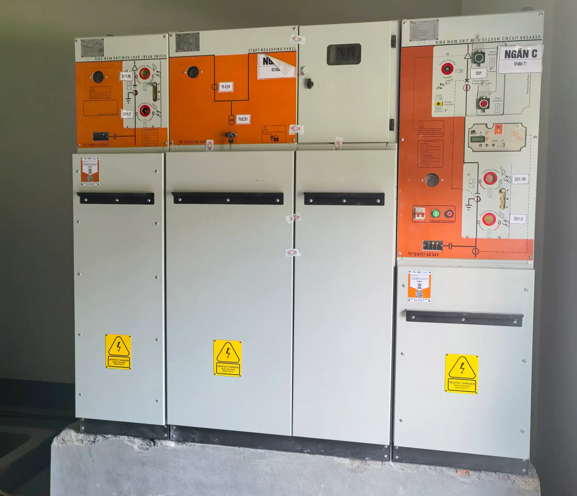
RMU Technologies: SF₆, Air, Solid Insulation and Vacuum
An RMU is not defined by one insulation technology. Different designs use different insulation and switching technologies to meet specific project requirements.
SF₆-Insulated RMU
SF₆ has traditionally been used in many compact medium voltage switchgear designs because it provides effective insulation within a relatively small enclosure.
However, projects using SF₆ equipment also need to consider gas management, environmental requirements, and applicable regulations.
SF₆-Free RMU
SF₆-free technologies have become increasingly relevant for projects with specific environmental requirements.
Modern solutions can use dry air or other alternative insulation technologies together with vacuum switching. When selecting this type of RMU, engineers should compare the rated voltage, current, short-circuit performance, footprint, maintenance requirements, and applicable local regulations.
Solid-Insulated RMU
Solid insulation uses dielectric materials around critical electrical components.
Some modern RMUs combine solid insulation with vacuum interrupters. This approach allows manufacturers to develop compact designs without using SF₆ gas.
Vacuum Circuit Breaker in RMU
A vacuum circuit breaker can be integrated into an RMU when the application requires circuit breaker-based protection.
Compared with a basic fuse-switch arrangement, this configuration can provide more flexible protection, remote operation, and fault management.
However, a VCB-based RMU is not automatically equivalent to a full modular MV switchgear lineup. Engineers should also compare the busbar arrangement, protection functions, feeder configuration, and expansion capability.
Common Misconceptions About RMU and MV Switchgear
Is RMU a Type of Switchgear?
Yes. An RMU is a type of medium voltage switchgear mainly designed for compact secondary distribution and ring network applications.
Does RMU Always Use SF₆?
No. Depending on the design, RMUs can use SF₆, dry air, clean air, solid insulation, and other technologies.
Is RMU Maintenance-Free?
No. Sealed designs can reduce some internal maintenance, but the complete installation still requires inspection and testing according to the manufacturer’s instructions.
Does RMU Automatically Provide Backup Power?
No. An RMU can support a ring or dual-source network, but it does not create an additional power source. Backup supply depends on the network design and available alternative source.
Is MV Switchgear Always Larger Than an RMU?
Not necessarily. Modular MV switchgear often requires more space when several functional panels are included, but actual dimensions vary between product designs.
Is RMU Always More Cost-Effective?
Not necessarily. Total project cost also depends on installation space, civil works, protection, automation, maintenance, expansion, and lifecycle requirements.
FAQs
1. What is the main difference between RMU and MV switchgear?
RMU is a specialized type of medium voltage switchgear designed mainly for compact secondary distribution and ring network applications. Conventional MV switchgear provides a broader range of configurations for feeders, protection, metering, and expansion.
2. Can RMU be used for solar PV and BESS projects?
RMUs can be used at transformer substations, collection points, and other MV sections of renewable energy systems. However, protection, communication, automation, and grid requirements should be reviewed before selecting the equipment.
3. Does RMU provide better reliability than conventional switchgear?
Equipment type alone does not determine system reliability. Network topology, protection coordination, maintenance, automation, equipment quality, and alternative power sources all affect reliability.
4. When should I choose VCB switchgear instead of an RMU?
VCB-based MV switchgear may be considered when the project requires multiple feeders, complex protection coordination, detailed metering, advanced control, or significant future expansion.
A circuit breaker-based RMU may also meet some of these requirements, so engineers should review the complete configuration before making the final selection.
5. Can RMU and conventional MV switchgear be used in the same project?
Of course. For example, a large industrial park may use modular MV switchgear at the main distribution substation and RMUs at individual transformer substations or ring network points.
This approach allows different sections of the electrical system to use configurations that match their specific distribution and protection requirements.
Conclusion
Choosing between RMU and MV switchgear depends on your system voltage, load, fault level, protection scheme, feeder configuration, installation space, and future requirements.
If you are unsure which configuration fits your project, share your electrical specifications or project drawings with our engineers. We can review the requirements and help you identify a suitable MV switchgear or RMU configuration.